Toyota Tacoma (2015-2018) Service Manual: System Diagram
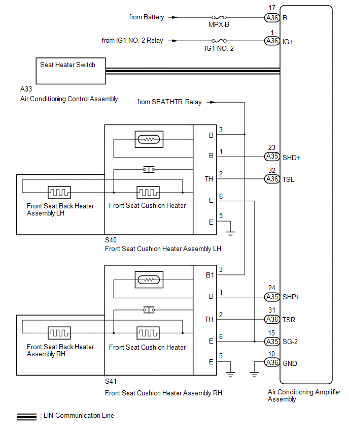
SYSTEM DIAGRAM
 Precaution
PRECAUTION
1. EXPRESSIONS OF IGNITION SWITCH
The type of ignition switch used on this model differs depending on the specifications
of the vehicle. The expressions listed in the table below are us ...
 How To Proceed With Troubleshooting
CAUTION / NOTICE / HINT
HINT:
Use this procedure to troubleshoot the seat heater system.
*: Use the Techstream.
PROCEDURE
1.
VEHICLE BROUGHT TO WORKSHOP
...
Other materials:
Data List / Active Test
DATA LIST / ACTIVE TEST
1. DATA LIST
HINT:
Using the Techstream to read the Data List allows the values or states of switches,
sensors, actuators and other items to be read without removing any parts. This non-intrusive
inspection can be very useful because intermittent conditions or signals ...
Installation
INSTALLATION
CAUTION / NOTICE / HINT
HINT:
Perform "Inspection After Repairs" after replacing the fuel delivery pipe assembly
LH (fuel pressure sensor) (See page ).
PROCEDURE
1. INSTALL FUEL PIPE PLUG SUB-ASSEMBLY
(a) Install a new O-ring, new No. 1 fuel injector back-up ring, new ...
Front Passenger Side Power Window does not Operate with Front Passenger Side
Power Window Switch
DESCRIPTION
When the engine is running or the ignition switch is ON, the front power window
regulator motor assembly RH is operated by the front power window regulator switch
assembly RH. The front power window regulator motor assembly RH has motor, regulator,
and ECU functions.
HINT:
If th ...
