Toyota Tacoma (2015-2018) Service Manual: System Diagram
SYSTEM DIAGRAM
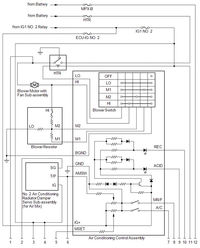
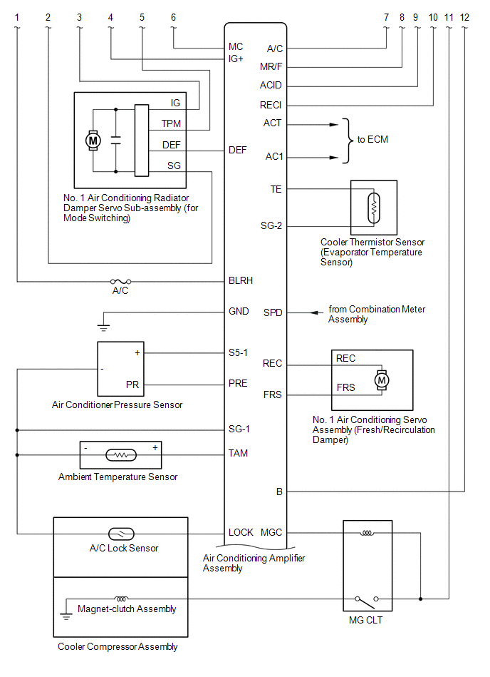
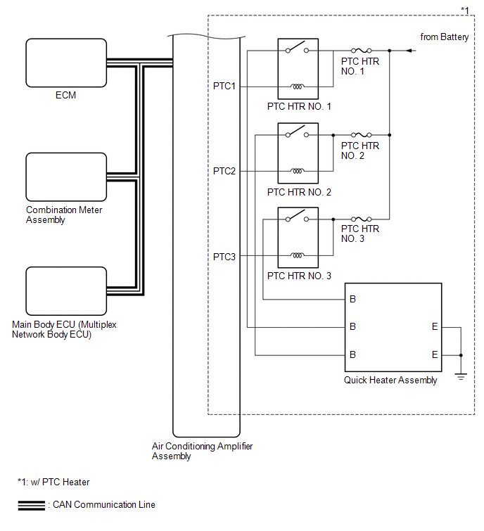
 System Description
SYSTEM DESCRIPTION
1. GENERAL
(a) The air conditioning system has the following controls.
Control
Outline
Manual Control
The air conditioner amplif ...
 Problem Symptoms Table
PROBLEM SYMPTOMS TABLE
HINT:
Use the table below to help determine the cause of problem symptoms.
If multiple suspected areas are listed, the potential causes of the symptoms
are lis ...
Other materials:
Disassembly
DISASSEMBLY
PROCEDURE
1. REMOVE MILLIMETER WAVE RADAR WIRE (w/ Toyota Safety Sense P)
Click here
2. REMOVE MILLIMETER WAVE RADAR SENSOR ASSEMBLY (w/ Toyota Safety Sense P)
Click here
3. REMOVE NO. 1 RADIATOR GRILLE GARNISH
(a) When Replacing the No. 1 Radiator Grille Garnish:
(1) Apply p ...
Vehicle Speed Signal Circuit between Stereo Component Amplifier and Combination
Meter
DESCRIPTION
The stereo component amplifier assembly receives a vehicle speed signal from
the combination meter assembly to control the ASL function.
HINT:
A voltage of 12 V or 5 V is output from each ECU and then input to the
combination meter assembly. The signal is changed to a pu ...
Antenna Coil Open / Short (B2784)
DESCRIPTION
When an open or short circuit is detected in the transponder key amplifier coil
built into the engine switch, the certification ECU (smart key ECU assembly) stores
this DTC. This DTC is also stored as a past DTC.
DTC Code
DTC Detection Condition
Tro ...
