Toyota Tacoma (2015-2018) Service Manual: Antenna Coil Open / Short (B2784)
DESCRIPTION
When an open or short circuit is detected in the transponder key amplifier coil built into the engine switch, the certification ECU (smart key ECU assembly) stores this DTC. This DTC is also stored as a past DTC.
|
DTC Code |
DTC Detection Condition |
Trouble Area |
DTC Output Confirmation Operation |
|---|---|---|---|
|
B2784 |
The transponder key amplifier coil built into the engine switch is open (see below) or shorted (determined by communication with certification ECU (smart key ECU assembly)) (1 trip detection logic*).
|
|
With the shift lever in P, the key held near the engine switch and an engine start operation is performed by pressing and holding the engine switch when the key battery is depleted. |
- *: Only output while a malfunction is present.
|
Vehicle Condition when Malfunction Detected |
Fail-safe Operation when Malfunction Detected |
|---|---|
|
Engine cannot be started when key battery is depleted by holding key near engine switch and pressing and holding engine switch with shift lever in P |
- |
|
DTC Code |
Data List and Active Test |
|---|---|
|
B2784 |
- |
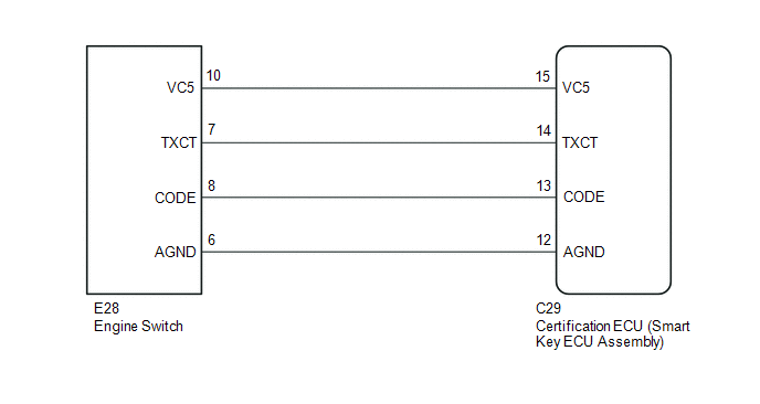
WIRING DIAGRAM
CAUTION / NOTICE / HINT
NOTICE:
- Before replacing the certification ECU (smart key ECU assembly), refer
to Registration (See page
.gif) ).
). - After performing repairs, perform the operation that fulfills the DTC output confirmation operation, and then confirm that no DTCs are output again.
PROCEDURE
|
1. |
CLEAR DTC |
(a) Clear the DTCs (See page ).
|
.gif)
|
2. |
CHECK DTC OUTPUT |
(a) Perform "DTC Output Confirmation Operation" procedure.
(b) Check for DTCs (See page ).
OK:
DTC B2784 is not output.
| OK | .gif) |
USE SIMULATION METHOD TO CHECK |
|
|
3. |
CHECK ENGINE SWITCH (OUTPUT) |
(a) Using an oscilloscope, check the waveform.
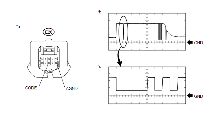 Text in Illustration
|
*a |
Component with harness connected (Engine Switch) |
*b |
Waveform |
|
*c |
Waveform (detail) |
- |
- |
Measurement Condition:
|
Tester Connection |
Condition |
Tool Setting |
Specified Condition |
|---|---|---|---|
|
E28-8 (CODE) - E28-6 (AGND) |
Engine switch off, engine switch pressed with key held near engine switch* |
1 V/DIV., 20 ms./DIV. |
Pulse generation (See waveform) |
|
2 V/DIV., 100 ÎĽs./DIV. |
Pulse generation (See waveform (detail)) |
- *: Remove the key battery before performing this inspection.
OK:
The waveform is similar to that shown in the illustration
| NG | |
REPLACE ENGINE SWITCH |
|
|
4. |
REPLACE CERTIFICATION ECU (SMART KEY ECU ASSEMBLY) |
(a) Replace the certification ECU (smart key ECU assembly) with a new one (See
page ).
|
|
5. |
REGISTER RECOGNITION CODE |
(a) Register the key (See page ).
|
|
6. |
REGISTER ECU COMMUNICATION ID |
(a) Register the ECU communication ID (See page
).
|
|
7. |
CLEAR DTC |
(a) Clear the DTCs (See page ).
|
|
8. |
CHECK FOR DTC |
(a) Perform "DTC Output Confirmation Operation" procedure.
(b) Check for DTCs (See page ).
OK:
DTC B2784 is not output.
| OK | |
END (CERTIFICATION ECU (SMART KEY ECU ASSEMBLY) WAS DEFECTIVE) |
| NG | |
REPLACE ENGINE SWITCH |
 Engine Immobiliser System Incorrect Assembly (B279C95)
DESCRIPTION
This code is stored when an ECM that is incompatible with the engine immobiliser
system is installed to the vehicle.
DTC Code
DTC Detection Condition
T ...
 Engine Immobiliser System Signal (Some Circuit Quantity, Reported via Serial
Data) Invalid (B279986)
Engine Immobiliser System Signal (Some Circuit Quantity, Reported via Serial
Data) Invalid (B279986)
DESCRIPTION
When there are communication malfunctions between the ECM and certification ECU
(smart key ECU assembly), or when the communication ID codes do not match, the ECM
stores this DTC.
...
Other materials:
Short to +B in Outer Mirror Indicator(Slave) (C1AB1)
DESCRIPTION
This DTC is stored when the blind spot monitor sensor RH detects a +B short in
the blind spot monitor indicator RH.
DTC Code
DTC Detection Condition
Trouble Area
C1AB1
With the blind spot monitor main switch assembly (warni ...
Parts Location
PARTS LOCATION
ILLUSTRATION
*A
for Automatic Transmission
-
-
*1
FRONT SPEED SENSOR LH
*2
FRONT SPEED SENSOR RH
*3
FRONT AXLE WITH ABS ROTOR BEARING ASSEMBLY LH
- FRONT SP ...
Dtc Check / Clear
DTC CHECK / CLEAR
1. CHECK DTC (CHECK USING TECHSTREAM)
(a) Connect the Techstream to the DLC3.
(b) Turn the ignition switch to ON.
(c) Turn the Techstream on.
(d) Enter the following menus: Body Electrical / Navigation System / Trouble
Codes.
(e) Check for DTCs, and then write them down.
( ...
