Toyota Tacoma (2015-2018) Service Manual: Status Signal Circuit
DESCRIPTION
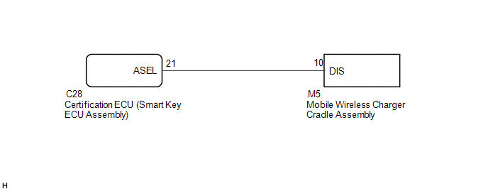
This circuit sends a smart key system status signal from the certification ECU (smart key ECU assembly) to the mobile wireless charger cradle assembly. Based on this signal, the mobile wireless charger cradle assembly suspends or resumes wireless charging.
WIRING DIAGRAM
CAUTION / NOTICE / HINT
NOTICE:
Before replacing the certification ECU (smart key ECU assembly), refer to the
Registration ( .gif) ).
).
PROCEDURE
|
1. |
INSPECT MOBILE WIRELESS CHARGER CRADLE ASSEMBLY |
|
(a) Measure the voltage according to the value(s) in the table below. Text in Illustration
Standard Voltage:
HINT:
|
|
| OK | .gif) |
PROCEED TO NEXT SUSPECTED AREA SHOWN IN PROBLEM SYMPTOMS TABLE |
|
.gif)
|
2. |
CHECK HARNESS AND CONNECTOR (MOBILE WIRELESS CHARGER CRADLE ASSEMBLY - CERTIFICATION ECU (SMART KEY ECU ASSEMBLY)) |
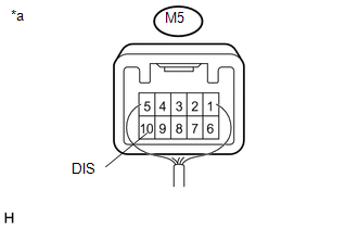
(a) Disconnect the M5 mobile wireless charger cradle assembly connector.
(b) Disconnect the C28 certification ECU (smart key ECU assembly) connector.
(c) Measure the resistance according to the value(s) in the table below.
Standard Resistance:
|
Tester Connection |
Condition |
Specified Condition |
|---|---|---|
|
M5-10 (DIS) - C28-21 (ASEL) |
Always |
Below 1 Ω |
|
M5-10 (DIS) - Body ground |
Always |
10 kΩ or higher |
| OK | |
REPLACE CERTIFICATION ECU (SMART KEY ECU ASSEMBLY) |
| NG | |
REPAIR OR REPLACE HARNESS OR CONNECTOR |
 Main Switch Signal Circuit
DESCRIPTION
When the wireless charger main switch (mobile wireless charger switch) is turned
on, this circuit sends an on signal to the mobile wireless charger cradle assembly
using the power sup ...
 Wireless Charger Illumination Circuit
DESCRIPTION
When the light control switch is turned to the tail or head position, this circuit
sends an illumination signal to the mobile wireless charger cradle assembly. Based
on this signal, t ...
Other materials:
Vehicle Speed Sensor Circuit (C1AA3)
DESCRIPTION
The forward recognition camera receives vehicle speed signals from the skid control
ECU. If the skid control ECU receives a vehicle speed sensor malfunction signal,
it informs the forward recognition camera via CAN communication, and DTC C1AA3 is
stored.
DTC No.
...
Problem Symptoms Table
PROBLEM SYMPTOMS TABLE
HINT:
Use the table below to help determine the cause of problem symptoms. If multiple
suspected areas are listed, the potential causes of the symptoms are listed in order
of probability in the "Suspected Area" column of the table. Check each symptom by
check ...
System Diagram
SYSTEM DIAGRAM
Communication Table
Transmitting ECU (Transmitter)
Receiving ECU (Receiver)
Signal
Line
Main body ECU
(Multiplex Network Body ECU)
Combination Meter Assembly
Wireless door lock hazard warnin ...
