Toyota Tacoma (2015-2018) Service Manual: Short to +B in Outer Mirror Indicator(Slave) (C1AB1)
DESCRIPTION
This DTC is stored when the blind spot monitor sensor RH detects a +B short in the blind spot monitor indicator RH.
|
DTC Code |
DTC Detection Condition |
Trouble Area |
|---|---|---|
|
C1AB1 |
With the blind spot monitor main switch assembly (warning canceling switch assembly) on, the voltage applied to the indicator is high for a certain amount of time even though the blind spot monitor sensor is not outputting voltage to the indicator. |
|
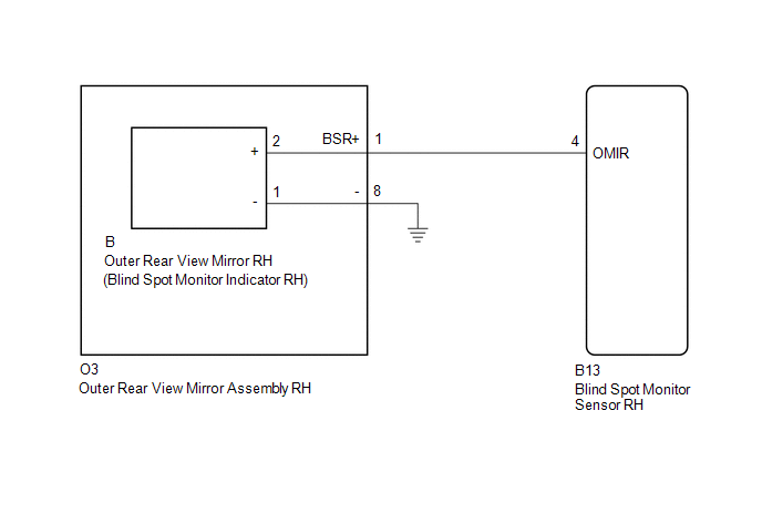
WIRING DIAGRAM
CAUTION / NOTICE / HINT
NOTICE:
When checking for DTCs, make sure that the blind spot monitor main switch assembly (warning canceling switch assembly) is on.
PROCEDURE
|
1. |
CHECK DTC |
(a) Clear the DTCs (See page .gif) ).
).
(b) Recheck for DTCs and check if the same DTC is output again (See page
).
OK:
No DTCs are output.
| OK | .gif) |
USE SIMULATION METHOD TO CHECK |
|
.gif)
|
2. |
CHECK HARNESS AND CONNECTOR (OUTER REAR VIEW MIRROR INDICATOR RH CIRCUIT) |
|
(a) Disconnect the blind spot monitor sensor RH connector. |
|
.png)
(b) Measure the voltage according to the value(s) in the table below.
Standard Voltage:
|
Tester Connection |
Switch Condition |
Specified Condition |
|---|---|---|
|
B13-4 (OMIR) - Body ground |
Ignition switch ON |
Below 1 V |
|
*a |
Front view of wire harness connector (to Blind Spot Monitor Sensor RH) |
| OK | |
REPLACE BLIND SPOT MONITOR SENSOR RH |
|
|
3. |
CHECK HARNESS AND CONNECTOR (BLIND SPOT MONITOR SENSOR RH - OUTER REAR VIEW MIRROR ASSEMBLY RH) |
|
(a) Disconnect the blind spot monitor sensor RH connector. |
|
(b) Disconnect the O3 outer rear view mirror assembly RH connector.
(c) Measure the voltage according to the value(s) in the table below.
Standard Voltage:
|
Tester Connection |
Switch Condition |
Specified Condition |
|---|---|---|
|
B13-4 (OMIR) - Body ground |
Ignition switch ON |
Below 1 V |
|
*a |
Front view of wire harness connector (to Blind Spot Monitor Sensor RH) |
| NG | |
REPAIR OR REPLACE HARNESS OR CONNECTOR |
|
|
4. |
CHECK HARNESS AND CONNECTOR (BLIND SPOT MONITOR SENSOR RH - OUTER REAR VIEW MIRROR RH) |
(a) Reconnect the O3 outer rear view mirror assembly RH connector.
|
(b) Disconnect the blind spot monitor sensor RH connector. |
|
(c) Disconnect the B outer rear view mirror RH connector.
(d) Measure the voltage according to the value(s) in the table below.
Standard Voltage:
|
Tester Connection |
Switch Condition |
Specified Condition |
|---|---|---|
|
B13-4 (OMIR) - Body ground |
Ignition switch ON |
Below 1 V |
|
*a |
Front view of wire harness connector (to Blind Spot Monitor Sensor RH) |
| OK | |
REPLACE OUTER REAR VIEW MIRROR RH |
| NG | |
REPLACE OUTER REAR VIEW MIRROR ASSEMBLY RH |
 Short to GND in Outer Mirror Indicator(Slave) (C1AB3)
DESCRIPTION
This DTC is stored when the blind spot monitor sensor RH detects a ground short
in the blind spot monitor indicator RH.
DTC Code
DTC Detection Condition
...
 Vehicle Speed Sensor (C1A45)
DESCRIPTION
The blind spot monitor sensor receives vehicle speed signals from the skid control
ECU (brake actuator assembly) via CAN communication.
DTC Code
DTC Detection Con ...
Other materials:
LIN Communication Bus Malfunction (B2325)
DESCRIPTION
The main body ECU (multiplex network body ECU) monitors communication between
all the ECUs connected to the door bus lines. When the main body ECU (multiplex
network body ECU) detects errors in communication with all the ECUs connected to
the door bus lines at 2.6-second intervals ...
Components
COMPONENTS
ILLUSTRATION
ILLUSTRATION
ILLUSTRATION
ILLUSTRATION
ILLUSTRATION
ILLUSTRATION
ILLUSTRATION
ILLUSTRATION
ILLUSTRATION
ILLUSTRATION
...
Power Source Mode does not Change to ON (ACC)
DESCRIPTION
If the engine switch is pressed with the electrical key transmitter sub-assembly
in the cabin, the certification ECU (smart key ECU assembly) receives a signal and
changes the power source mode.
HINT:
When the cable is disconnected and reconnected to the negative (-) battery termi ...
