Toyota Tacoma (2015-2018) Service Manual: LIN Communication Bus Malfunction (B2325)
DESCRIPTION
The main body ECU (multiplex network body ECU) monitors communication between all the ECUs connected to the door bus lines. When the main body ECU (multiplex network body ECU) detects errors in communication with all the ECUs connected to the door bus lines at 2.6-second intervals and 3 times in a row, DTC B2325 will be stored.
|
DTC No. |
DTC Detection Condition |
Trouble Area |
|---|---|---|
|
B2325 |
Main body ECU (multiplex network body ECU) detects errors in communication with the ECUs connected to the door bus lines 3 times in a row. |
|
- *1: w/ Jam Protection Function
- *2: w/ Sliding Roof
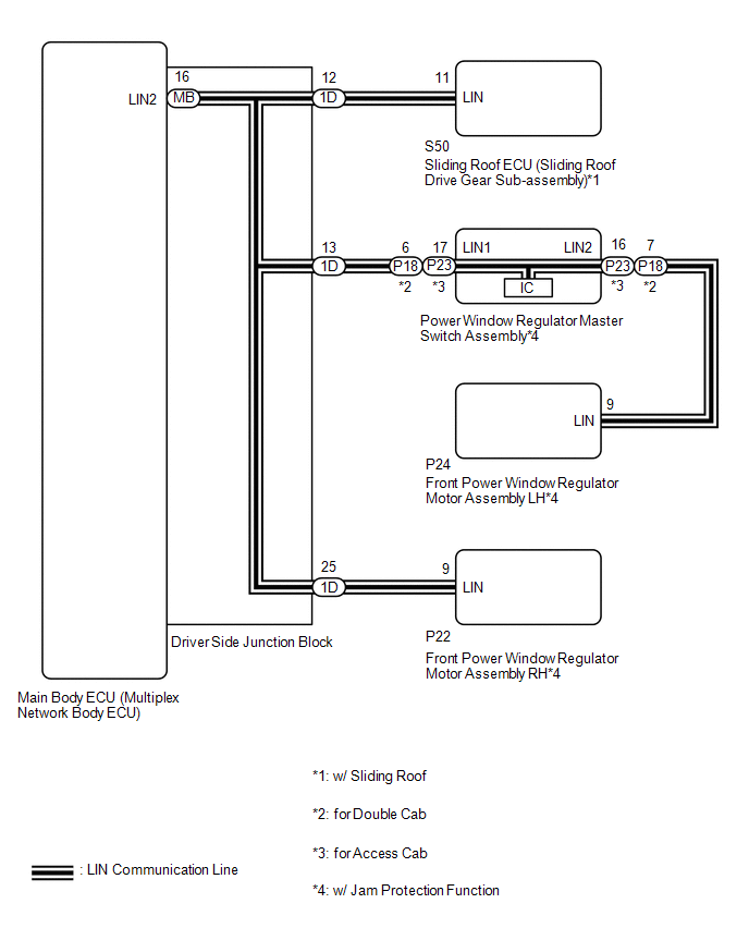
WIRING DIAGRAM
CAUTION / NOTICE / HINT
NOTICE:
- When the sliding roof ECU (sliding roof drive gear sub-assembly) is
replaced or removed and reinstalled, it requires initialization (See page
.gif) ).
). - If the main body ECU (multiplex network body ECU) is replaced, refer
to Registration (See page )
- When a power window regulator motor assembly is replaced or removed
and reinstalled, it requires initialization (See page
).
PROCEDURE
|
1. |
SYSTEM CHECK |
(a) Check the vehicle specification.
Result|
Result |
Proceed to |
|---|---|
|
w/ Jam Protection Function |
A |
|
w/o Jam Protection Function |
B |
| NG | .gif) |
GO TO STEP 4 |
|
.gif)
|
2. |
CHECK HARNESS AND CONNECTOR (POWER WINDOW REGULATOR MASTER SWITCH ASSEMBLY - FRONT POWER WINDOW REGULATOR MOTOR ASSEMBLY LH) |
(a) for Double Cab
(1) Disconnect the P18 power window regulator master switch assembly connector.
(2) Disconnect the P24 front power window regulator motor assembly LH connector.
(3) Measure the resistance according to the value(s) in the table below.
Standard Resistance:
|
Tester Connection |
Condition |
Specified Condition |
|---|---|---|
|
P18-7 (LIN2) - P24-9 (LIN) |
Always |
Below 1 Ω |
|
P18-7 (LIN2) or P24-9 (LIN) - Body ground |
Always |
10 kΩ or higher |
(b) for Access Cab
(1) Disconnect the P23 power window regulator master switch assembly connector.
(2) Disconnect the P24 front power window regulator motor assembly LH connector.
(3) Measure the resistance according to the value(s) in the table below.
Standard Resistance:
|
Tester Connection |
Condition |
Specified Condition |
|---|---|---|
|
P23-16 (LIN2) - P24-9 (LIN) |
Always |
Below 1 Ω |
|
P23-16 (LIN2) or P24-9 (LIN) - Body ground |
Always |
10 kΩ or higher |
| NG | |
REPAIR OR REPLACE HARNESS OR CONNECTOR |
|
|
3. |
INSPECT POWER WINDOW REGULATOR MASTER SWITCH ASSEMBLY |
(a) for Double Cab
|
(1) Remove the power window regulator master switch assembly. |
|
.png)
(2) Measure the resistance according to the value(s) in the table below.
Standard Resistance:
|
Tester Connection |
Condition |
Specified Condition |
|---|---|---|
|
6 (LIN1) - 7 (LIN2) |
Always |
Below 1 Ω |
|
*a |
Component without harness connected (Power Window Regulator Master Switch Assembly) |
(b) for Access Cab
|
(1) Remove the power window regulator master switch assembly. |
|
.png)
(2) Measure the resistance according to the value(s) in the table below.
Standard Resistance:
|
Tester Connection |
Condition |
Specified Condition |
|---|---|---|
|
17 (LIN1) - 16 (LIN2) |
Always |
Below 1 Ω |
|
*a |
Component without harness connected (Power Window Regulator Master Switch Assembly) |
| NG | |
REPLACE POWER WINDOW REGULATOR MASTER SWITCH ASSEMBLY |
|
|
4. |
INSPECT DRIVER SIDE JUNCTION BLOCK |
(a) Remove the driver side junction block (See page
).
(b) Remove the main body ECU (multiplex network body ECU) from the driver side junction block.
(c) Measure the resistance according to the value(s) in the table below.
.png)
Standard Resistance:
|
Tester Connection |
Condition |
Specified Condition |
|---|---|---|
|
1D-12 - MB-16 (LIN2)*1 |
Always |
Below 1 Ω |
|
1D-13 - MB-16 (LIN2)*2 |
Always |
Below 1 Ω |
|
1D-25 - MB-16 (LIN2)*2 |
Always |
Below 1 Ω |
- *1: w/ Sliding Roof
- *2: w/ Jam Protection Function
|
*a |
Component without harness connected (Driver Side Junction Block) |
- |
- |
HINT:
This inspection is to check the LIN line in the driver side junction block that connects the wire harness to the built-in main body ECU (multiplex network body ECU).
| NG | |
REPLACE DRIVER SIDE JUNCTION BLOCK |
|
|
5. |
CHECK HARNESS AND CONNECTOR (DRIVER SIDE JUNCTION BLOCK - EACH ECU) |
(a) Disconnect the P22 front power window regulator motor assembly RH connector.*1
(b) Disconnect the P18*2 or P23*3 power window regulator master switch assembly connector.*1
(c) Disconnect the S50 sliding roof ECU (sliding roof drive gear sub-assembly) connector.*4
(d) Measure the resistance according to the value(s) in the table below.
Standard Resistance:
|
Tester Connection |
Condition |
Specified Condition |
|---|---|---|
|
1D-25 - P22-9 (LIN)*1 |
Always |
Below 1 Ω |
|
1D-13 - P18-6 (LIN1)*1*2 |
Always |
Below 1 Ω |
|
1D-13 - P23-17 (LIN1)*1*3 |
Always |
Below 1 Ω |
|
1D-12 - S50-11 (LIN)*4 |
Always |
Below 1 Ω |
|
1D-25 - Body ground*1 |
Always |
10 kΩ or higher |
|
1D-13 - Body ground*1 |
Always |
10 kΩ or higher |
|
1D-12 - Body ground*4 |
Always |
10 kΩ or higher |
- *1: w/ Jam Protection Function
- *2: for Double Cab
- *3: for Access Cab
- *4: w/ Sliding Roof
|
Result |
Proceed to |
|---|---|
|
OK (w/ Jam Protection Function) |
A |
|
OK (w/o Jam Protection Function) |
B |
|
NG |
C |
| B | |
GO TO STEP 9 |
| C | |
REPAIR OR REPLACE HARNESS OR CONNECTOR |
|
|
6. |
CHECK DTC OUTPUT (POWER WINDOW REGULATOR MASTER SWITCH ASSEMBLY) |
(a) Reconnect the P24 front power window regulator motor assembly LH connector.
(b) Reconnect the P22 front power window regulator motor assembly RH connector.
(c) Reconnect the S50 sliding roof ECU (sliding roof drive gear sub-assembly) connector.*1
(d) Reconnect the 1D driver side junction block connector.
(e) Clear the DTCs (See page ).
(f) After 10 seconds have elapsed, check if the trouble occurs again.
(g) Check for DTCs again.
- *1: w/ Sliding Roof
|
Result |
Proceed to |
|---|---|
|
DTC B2325 is output |
A |
|
DTC B2325 is not output |
B |
| B | |
REPLACE POWER WINDOW REGULATOR MASTER SWITCH ASSEMBLY |
|
|
7. |
CHECK DTC OUTPUT (FRONT POWER WINDOW REGULATOR MOTOR ASSEMBLY LH) |
(a) Reconnect the P18*1 or P23*2 power window regulator master switch assembly connector.
(b) Disconnect the P24 front power window regulator motor assembly LH connector.
(c) Clear the DTCs (See page ).
(d) After 10 seconds have elapsed, check if the trouble occurs again.
(e) Check for DTCs again.
- *1: for Double Cab
- *2: for Access Cab
|
Result |
Proceed to |
|---|---|
|
DTC B2325 is output |
A |
|
DTC B2325 is not output |
B |
| B | |
REPLACE FRONT POWER WINDOW REGULATOR MOTOR ASSEMBLY LH |
|
|
8. |
CHECK DTC OUTPUT (FRONT POWER WINDOW REGULATOR MOTOR ASSEMBLY RH) |
(a) Reconnect the P24 front power window regulator motor assembly LH connector.
(b) Disconnect the P22 front power window regulator motor assembly RH connector.
(c) Clear the DTCs (See page ).
(d) After 10 seconds have elapsed, check if the trouble occurs again.
(e) Check for DTCs again.
|
Result |
Proceed to |
|---|---|
|
DTC B2325 is output (w/ Sliding Roof) |
A |
|
DTC B2325 is output (w/o Sliding Roof) |
B |
|
DTC B2325 is not output |
C |
| B | |
REPLACE MAIN BODY ECU (MULTIPLEX NETWORK BODY ECU) |
| C | |
REPLACE FRONT POWER WINDOW REGULATOR MOTOR ASSEMBLY RH |
|
|
9. |
CHECK DTC OUTPUT (SLIDING ROOF ECU (SLIDING ROOF DRIVE GEAR SUB-ASSEMBLY)) |
(a) Reconnect the P22 front power window regulator motor assembly RH connector.*1
(b) Disconnect the S50 sliding roof ECU (sliding roof drive gear sub-assembly) connector.
(c) Clear the DTCs (See page ).
(d) After 10 seconds have elapsed, check if the trouble occurs again.
(e) Check for DTCs again.
- *1: w/ Jam Protection Function
|
Result |
Proceed to |
|---|---|
|
DTC B2325 is output |
A |
|
DTC B2325 is not output |
B |
| A | |
REPLACE MAIN BODY ECU (MULTIPLEX NETWORK BODY ECU) |
| B | |
REPLACE SLIDING ROOF ECU (SLIDING ROOF DRIVE GEAR SUB-ASSEMBLY) |
 Driver Side Door ECU Communication Stop (B2321)
DESCRIPTION
This DTC is stored when LIN communication between the front power window regulator
motor assembly LH and main body ECU (multiplex network body ECU) stops for 10 seconds
or more.
...
 P/W Master Switch Communication Stop (B1206)
DESCRIPTION
This DTC is stored when LIN communication between the power window regulator
master switch assembly and main body ECU (multiplex network body ECU) stops for
10 seconds or more.
...
Other materials:
Fender Panel Mudguard
Components
COMPONENTS
ILLUSTRATION
ILLUSTRATION
Installation
INSTALLATION
CAUTION / NOTICE / HINT
HINT:
Use the same procedure for the RH side and LH side.
The following procedure is for the LH side.
PROCEDURE
1. INSTALL FRONT FENDER MUDGUARD
(a) Install the fron ...
Sliding Roof Switch Assembly
Components
COMPONENTS
ILLUSTRATION
Installation
INSTALLATION
PROCEDURE
1. INSTALL SLIDING ROOF SWITCH ASSEMBLY (ROOF CONSOLE BOX ASSEMBLY)
(a) Connect the connector.
(b) Engage the 4 clips to install the sliding roof switch assembly (roof console
box assembly).
Removal
REMOVAL
P ...
Distance Control Switch Circuit
DESCRIPTION
The distance control switch is used to set the distance for vehicle-to-vehicle
distance control mode. The distance control switch is installed in the steering
pad switch assembly. The vehicle-to-vehicle distance set value can be changed by
operating the steering pad switch assembl ...
