Toyota Tacoma (2015-2018) Service Manual: Replacement
REPLACEMENT
PROCEDURE
1. RECOVER REFRIGERANT FROM REFRIGERATION SYSTEM
(a) Start the engine.
(b) Operate the cooler compressor under the conditions shown below:
|
Item |
Condition |
|---|---|
|
Engine Speed |
Idling |
|
Operating Time |
3 minutes or more |
|
A/C Switch Status |
On |
|
Blower Switch Status |
HI |
|
Set Temperature |
MAX COOL |
This causes most of the compressor oil from the various components of the A/C system to collect in the A/C compressor.
NOTICE:
It is not necessary to operate the cooler compressor if the A/C does not operate because of compressor lock, etc.
(c) Stop the engine.
(d) Recover the refrigerant from the A/C system using a refrigerant recovery unit.
NOTICE:
Be sure to use a refrigerant recovery unit that is compatible with HFO-1234yf (R1234yf) systems.
HINT:
Use the refrigerant recovery unit in accordance with the manufacturer's instruction manual.
2. CHARGE AIR CONDITIONING SYSTEM WITH REFRIGERANT
HINT:
Charge refrigerant in accordance with the equipment manual.
(a) Perform vacuum purging using a refrigerant recover unit.
NOTICE:
Be sure to use a refrigerant recovery unit that is compatible with HFO-1234yf (R1234yf) systems.
(b) Charge refrigerant HFO-1234yf (R1234yf).
Standard:
480 to 540 g (16.93 to 19.05 oz.)
NOTICE:
Make sure the amount of refrigerant is within 30 g of the specified amount.
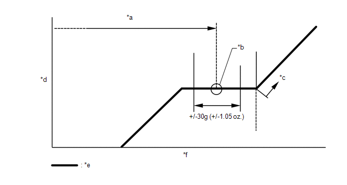 Text in Illustration
|
*a |
Amount to be charged |
*b |
Mean value in proper range |
|
*c |
Overcharged |
*d |
Pressure |
|
*e |
Sub-cool system |
*f |
Refrigerant amount |
NOTICE:
Do not operate the cooler compressor before charging refrigerant as the cooler compressor will not work properly without any refrigerant, and will overheat.
3. WARM UP ENGINE
(a) Warm up the engine at less than 1640 rpm for 2 minutes or more after charging the refrigerant.
NOTICE:
Be sure to warm up the compressor by turning the A/C switch on after removing and installing the cooler refrigerant lines (including the compressor) to prevent damage to the compressor.
4. INSPECT FOR REFRIGERANT LEAK
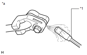
(a) After recharging the refrigerant, check for refrigerant gas leakage using a gas leak detector.
HINT:
Be sure to use a gas leak detector that is compatible with HFO-1234yf (R1234yf) systems.
(1) Perform the operation observing the following instructions:
- Stop the engine.
- Secure good ventilation (the gas leak detector may react to volatile gases other than refrigerant, such as evaporated gasoline or exhaust gas).
- Repeat the test 2 or 3 times.
- Make sure that some refrigerant remains in the refrigeration system.
HINT:
When the compressor is off: approximately 392 to 588 kPa (4.0 to 6.0 kgf/cm2, 57 to 85 psi).
|
(2) Using a gas leak detector, check the refrigerant line for leakage. |
|
(3) If a gas leak is not detected from the drain hose, remove the blower motor control (blower resistor) from the cooling unit. Insert the sensor of the gas leak detector into the unit and check for gas leakage.
(4) Disconnect the pressure switch connector and wait for approximately 20 minutes. Bring the gas leak detector close to the pressure switch and check for gas leakage.
Text in Illustration|
*1 |
Gas Leak Detector |
|
*a |
Check for Leakage |
 Precaution
PRECAUTION
1. PRECAUTIONS FOR REFRIGERANT HFO-1234yf (R1234yf)
(a) Compatibility
(1) The parts used in the refrigerant cycle, the compressor oil, etc. of the
HFO-1234yf (R1234yf) system are not c ...

Other materials:
Lost Communication With Vehicle Dynamics Control Module (U0122)
DESCRIPTION
This DTC is detected if communication is lost with the skid control ECU (brake
actuator assembly).
DTC No.
Detection Item
DTC Detection Condition
Trouble Area
U0122
Lost Communication with Vehicle Dynamics Contro ...
Definition Of Terms
DEFINITION OF TERMS
Term
Definition
Monitor description
Description of what the ECM monitors and how it detects malfunctions
(monitoring purpose and details).
Related DTCs
Group of diagnostic trouble codes that are ou ...
How To Proceed With Troubleshooting
CAUTION / NOTICE / HINT
Techstream can be used in steps 3, 6, 9 and 12.
PROCEDURE
1.
VEHICLE BROUGHT TO WORKSHOP
NEXT
2.
CUSTOMER PROBLEM ANALYSIS
...
