Toyota Tacoma (2015-2018) Service Manual: Removal
REMOVAL
PROCEDURE
1. REMOVE INTAKE MANIFOLD
(See page .gif) )
)
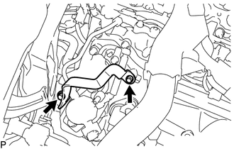
2. REMOVE WIRE HARNESS CLAMP BRACKET
|
(a) Remove the 2 bolts and wire harness clamp bracket. |
|
3. REMOVE FUEL TUBE SUB-ASSEMBLY
|
(a) Disconnect the fuel tube sub-assembly from the fuel pump assembly
(See page |
|
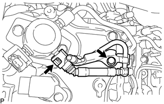
(b) Remove the bolt and fuel tube sub-assembly.
4. REMOVE NO. 1 FUEL PIPE SUB-ASSEMBLY
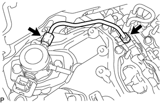
(a) Loosen the 2 union nuts of the No. 1 fuel pipe sub-assembly.
(b) Remove the No. 1 fuel pipe sub-assembly.
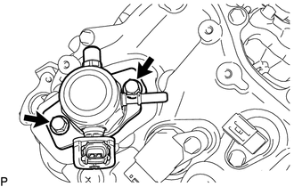
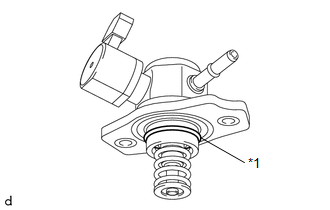
5. REMOVE FUEL PUMP ASSEMBLY
|
(a) Remove the 2 bolts and fuel pump assembly. |
|
|
(b) Remove the O-ring from the fuel pump assembly. |
|
(c) Remove the fuel pump lifter guide and fuel pump lifter assembly.
(d) Remove the fuel pump spacer gasket from the cylinder head cover sub-assembly.
 On-vehicle Inspection
ON-VEHICLE INSPECTION
PROCEDURE
1. CHECK FUEL PUMP ASSEMBLY OPERATION
(a) Check fuel pressure.
(1) Connect the Techstream to the DLC3.
(2) Start the engine.
(3) Turn the Techstream on.
(4) Ente ...
 Inspection
INSPECTION
PROCEDURE
1. INSPECT FUEL PUMP ASSEMBLY
(a) Measure the resistance according to the value(s) in the table below.
Standard Resistance:
Tester Connection
Condition ...
Other materials:
Low Power Supply Voltage Malfunction (C1241)
DESCRIPTION
If a malfunction is detected in the power supply circuit, the skid control ECU
(brake actuator assembly) stores this DTC and the fail-safe function prohibits ABS
operation.
This DTC is stored when the +BS terminal voltage deviates from the DTC detection
condition due to a malfunc ...
ABS Warning Light Remains ON
DESCRIPTION
If any of the following is detected, the ABS warning light remains on.
The skid control ECU (master cylinder solenoid) connectors are disconnected
from the skid control ECU (master cylinder solenoid).
There is a malfunction in the skid control ECU (master cylinder soleno ...
Removal
REMOVAL
PROCEDURE
1. PRECAUTION
NOTICE:
After turning the ignition switch off, waiting time may be required before disconnecting
the cable from the negative (-) battery terminal. Therefore, make sure to read the
disconnecting the cable from the negative (-) battery terminal notices before pr ...
