Toyota Tacoma (2015-2018) Service Manual: Installation
INSTALLATION
PROCEDURE
1. INSTALL PROPELLER SHAFT WITH CENTER BEARING ASSEMBLY
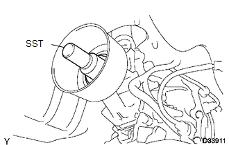
(a) Remove SST from the extension housing.
(b) Install the propeller shaft to the extension housing.
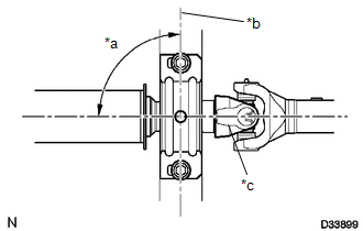
(c) Completely remove any oil or the like and clean the contact surfaces of the propeller shaft flange and differential flange.
|
(d) Align the matchmarks on the propeller shaft flange and differential flange. Text in Illustration
|
|
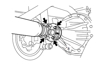
(e) for Differential Type BD20:
(1) Install the propeller shaft with the 4 bolts, 4 washers and 4 nuts.
Torque:
88 N·m {899 kgf·cm, 65 ft·lbf}
(f) for Differential Type BD22:
(1) Install the propeller shaft with the 4 washers and 4 nuts.
Torque:
88 N·m {899 kgf·cm, 65 ft·lbf}
|
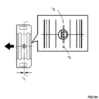
(g) Temporarily install the center No. 2 support bearing assembly with the 2 bolts. Text in Illustration
HINT: Make sure the bearing is installed with the drain hole facing downwards. |
|
|
(h) Adjust the center No. 2 support bearing assembly. Text in Illustration
HINT:
|
|
(i) Tighten the 2 bolts.
Torque:
36 N·m {369 kgf·cm, 27 ft·lbf}
2. INSPECT FOR TRANSMISSION OIL LEAK
 Inspection
INSPECTION
PROCEDURE
1. INSPECT PROPELLER SHAFT WITH CENTER BEARING ASSEMBLY
(a) Using a dial indicator, check the propeller shaft with center bearing assembly
runout.
Maximum runout:
0.6 mm ...
 Reassembly
REASSEMBLY
PROCEDURE
1. INSPECT CENTER NO. 2 SUPPORT BEARING ASSEMBLY
(a) When turning the center No. 2 support bearing assembly with your hand, check
that it turns smoothly without catching an ...
Other materials:
Customize Parameters
CUSTOMIZE PARAMETERS
1. CUSTOMIZING FUNCTION WITH TECHSTREAM
NOTICE:
When the customer requests a change in a function, first make sure that
the function can be customized.
Be sure to make a note of the current settings before customizing.
When troubleshooting a function, f ...
Lost Communication with ECM (U0100,U0142,U0155)
DESCRIPTION
DTC No.
DTC Detecting Condition
Trouble Area
U0100
No communication with ECM
CAN communication system
ECM
U0142
No communication with main body ECU
...
Removal
REMOVAL
PROCEDURE
1. REMOVE SPIRAL CABLE WITH SENSOR SUB-ASSEMBLY
(See page )
2. REMOVE WINDSHIELD WIPER SWITCH ASSEMBLY
3. REMOVE HEADLIGHT DIMMER SWITCH ASSEMBLY
(a) Disconnect the connector.
(b) Disengage the 3 claws to remove the he ...
