Toyota Tacoma (2015-2018) Service Manual: On-vehicle Inspection
ON-VEHICLE INSPECTION
PROCEDURE
1. CHECK FUEL PUMP ASSEMBLY OPERATION
(a) Check fuel pressure.
(1) Connect the Techstream to the DLC3.
(2) Start the engine.
(3) Turn the Techstream on.
(4) Enter the following menus: Powertrain / Engine / Active Test / Control the Target Fuel Pressure.
(5) Check that the fuel pressure fluctuates when the target fuel pressure changes.
HINT:
The target fuel pressure operation lowers the target fuel pressure by 12.5% or increases the target fuel pressure by 25%.
Standard:
Fuel pressure fluctuates in accordance with the Techstream operation.
If the result is not as specified, replace the fuel delivery pipe sub-assembly (fuel pressure sensor).
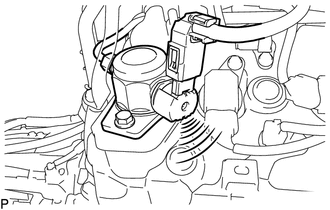
(b) Check operating sound.
(1) Remove the V-bank cover sub-assembly (See page
.gif) ).
).
(2) Start the engine.
|
(3) Using a sound scope, check the operating sound of the pump. If no sound can be heard, check the fuel pump, wire harness and ECM. |
|
(4) Stop the engine.
(5) Install the V-bank cover sub-assembly (See page
).
 Components
COMPONENTS
ILLUSTRATION
*1
FUEL PUMP ASSEMBLY
*2
FUEL PUMP LIFTER ASSEMBLY
*3
FUEL PUMP LIFTER GUIDE
*4
...
 Removal
REMOVAL
PROCEDURE
1. REMOVE INTAKE MANIFOLD
(See page )
2. REMOVE WIRE HARNESS CLAMP BRACKET
(a) Remove the 2 bolts and wire harness clamp bracket.
...
Other materials:
Installation
INSTALLATION
CAUTION / NOTICE / HINT
HINT:
The following procedures are for BD22 (w/o Differential Lock).
PROCEDURE
1. INSTALL DIFFERENTIAL CARRIER ASSEMBLY REAR
(a) Clean the contact surfaces of the rear differential carrier assembly and
axle housing.
(b) Install the rear differential carr ...
On-vehicle Inspection
ON-VEHICLE INSPECTION
PROCEDURE
1. INSPECT CAMSHAFT TIMING GEAR BOLT
(a) Remove the camshaft timing oil control solenoid assembly (See page
).
(b) Check that the plunger strokes when the plunger in the center of
the camshaft timing gear bolt is pressed.
Standard stroke:
4 ...
Lost Communication with Cruise Control Front Distance Range Sensor (U0235)
DESCRIPTION
The millimeter wave radar sensor assembly is connected to the skid control ECU
(master cylinder solenoid)*1 or skid control ECU (brake actuator assembly)*2 via
CAN communication. If communication with the skid control ECU (master cylinder solenoid)*1
or skid control ECU (brake act ...
