Toyota Tacoma (2015-2018) Service Manual: Removal
REMOVAL
CAUTION / NOTICE / HINT
NOTICE:
If one of the camshaft timing gear bolts is already removed, do not remove any other camshaft timing gear bolts.
PROCEDURE
1. REMOVE NO. 2 ENGINE UNDER COVER SUB-ASSEMBLY (w/ Off Road Package)
2. REMOVE NO. 1 ENGINE UNDER COVER SUB-ASSEMBLY
3. REMOVE CAMSHAFT TIMING OIL CONTROL SOLENOID ASSEMBLY
(See page .gif) )
)
4. SET NO. 1 CYLINDER TO TDC/COMPRESSION
|
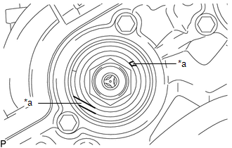
(a) Turn the crankshaft clockwise to align the timing mark (cutout) on the crankshaft pulley assembly with the "0" timing mark on the timing chain cover assembly. Text in Illustration
|
|
|
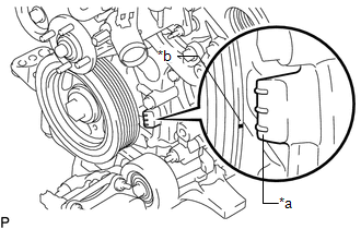
(b) Check that the end of the spring inside of the camshaft timing gear assembly is as shown in the illustration. Text in Illustration
HINT: If the end of the spring is not as shown in the illustration, rotate the crankshaft clockwise 360° and align the timing mark again. |
|
5. REMOVE CAMSHAFT TIMING GEAR BOLT
|
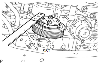
(a) Using SST, hold the crankshaft pulley assembly. SST: 09213-54015 91651-60855 SST: 09330-00021 |
|
|
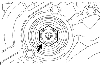
(b) Remove the camshaft timing gear bolt. NOTICE: Replace with a new part if it is dropped or if it receives a strong impact. |
|
 On-vehicle Inspection
ON-VEHICLE INSPECTION
PROCEDURE
1. INSPECT CAMSHAFT TIMING GEAR BOLT
(a) Remove the camshaft timing oil control solenoid assembly (See page
).
(b) Check that the plunger strokes when ...
 Installation
INSTALLATION
PROCEDURE
1. SET NO. 1 CYLINDER TO TDC/COMPRESSION
2. INSTALL CAMSHAFT TIMING GEAR BOLT
NOTICE:
There are different types of camshaft timing gear bolts. Make sure to check the
i ...
Other materials:
AUTO LSD Indicator Light does not Come ON
DESCRIPTION
The AUTO LSD does not operate even if the VSC OFF switch is pressed under the
following conditions:
The brake system is faulty.
The temperature inside the hydraulic brake booster increases and the
AUTO LSD operation is suspended.
WIRING DIAGRAM
CAUTION / NOTI ...
Diagnostic Trouble Code Chart
DIAGNOSTIC TROUBLE CODE CHART
VSC System
DTC Code
Detection Item
See page
C1201
Engine Control System Malfunction
C1203
ECM Communication Circuit Malfunction
C120B
...
Parts Location
PARTS LOCATION
ILLUSTRATION
ILLUSTRATION
ILLUSTRATION
ILLUSTRATION
...
