Toyota Tacoma (2015-2018) Service Manual: Removal
REMOVAL
PROCEDURE
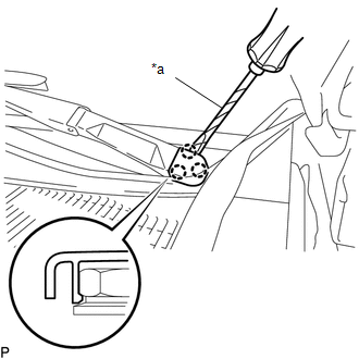
1. REMOVE FRONT WIPER ARM HEAD CAP
|
(a) Using a screwdriver with its tip wrapped in protective tape, disengage the 3 claws to remove the front wiper arm head cap. Text in Illustration
HINT: Use the same procedure for both sides. |
|
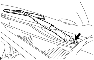
2. REMOVE WINDSHIELD WIPER ARM AND BLADE ASSEMBLY LH
|
(a) Remove the nut and windshield wiper arm and blade assembly LH. |
|
3. REMOVE WINDSHIELD WIPER ARM AND BLADE ASSEMBLY RH
HINT:
Use the same procedure as for the LH side.
4. REMOVE FRONT FENDER UPPER PROTECTOR LH
|
(a) Remove the clip. |
|
(b) Disengage the 3 clips to remove the front fender upper protector LH.
5. REMOVE FRONT FENDER UPPER PROTECTOR RH
HINT:
Use the same procedure as for the LH side.
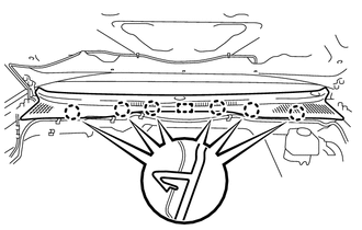
6. REMOVE COWL TOP VENTILATOR LOUVER SUB-ASSEMBLY
|
(a) Disengage the 6 claws and guide. |
|
|
(b) Disengage the 9 guides to remove the cowl top ventilator louver sub-assembly. |
|

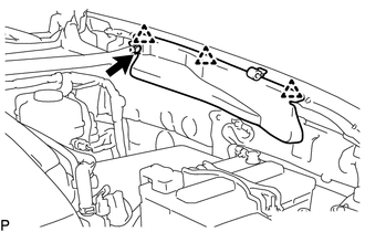
7. REMOVE WINDSHIELD WIPER MOTOR AND LINK
|
(a) Disconnect the connector. Text in Illustration
|
|
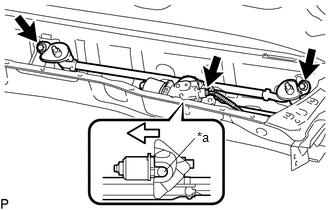
(b) Remove the 2 bolts.
(c) Disengage the motor grommet as shown in the illustration to remove the windshield wiper motor and link.
8. REMOVE WINDSHIELD WIPER MOTOR ASSEMBLY
|
(a) Using a screwdriver with its tip wrapped in protective tape, disengage the 2 rods at the crank arm pivot of the windshield wiper motor assembly. Text in Illustration
|
|

|
(b) Using a T30 "TORX" socket wrench, remove the 2 bolts and windshield wiper motor assembly. |
|

 Installation
INSTALLATION
PROCEDURE
1. INSTALL WINDSHIELD WIPER MOTOR ASSEMBLY
(a) Apply MP grease to the crank arm pivot of the windshield wiper motor
assembly.
Text in Illustration
...
 Front Wiper Rubber
Components
COMPONENTS
ILLUSTRATION
Installation
INSTALLATION
PROCEDURE
1. INSTALL FRONT WIPER RUBBER
(a) Install the 2 wiper rubber backing plates to the front wiper rubber.
...
Other materials:
Components
COMPONENTS
ILLUSTRATION
*1
FRONT ARMREST BASE UPPER PANEL SUB-ASSEMBLY
*2
FRONT DOOR GLASS INNER WEATHERSTRIP
*3
FRONT DOOR INSIDE HANDLE BEZEL PLUG
*4
FRONT DOOR INSIDE HANDLE SUB-ASSEMBLY
...
Operation History List
OPERATION HISTORY LIST
NOTICE:
The cause of a malfunction is stored in the RAM or EEPROM in the certification
ECU (smart key ECU assembly). As the cause of a malfunction stored in the
RAM will be cleared when the cable is disconnected from the negative (-)
battery terminal, do ...
System Description
SYSTEM DESCRIPTION
1. WIRELESS DOOR LOCK CONTROL SYSTEM
The wireless door lock control system functions to lock and unlock all the doors
from a distance. The system is controlled by a door control transmitter module set
sub-assembly which sends radio waves to the door control receiver. The mai ...
