Toyota Tacoma (2015-2018) Service Manual: Installation
INSTALLATION
PROCEDURE
1. INSTALL WINDSHIELD WIPER MOTOR ASSEMBLY
|
(a) Apply MP grease to the crank arm pivot of the windshield wiper motor assembly. Text in Illustration
|
|
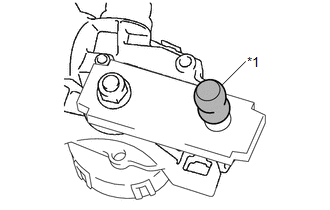
(b) Using a T30 "TORX" socket wrench, install the front wiper motor assembly with the 2 bolts.
Torque:
7.5 N·m {76 kgf·cm, 66 in·lbf}
|
(c) Install the 2 rods to the crank arm pivot of the windshield wiper motor assembly. |
|

2. INSTALL WINDSHIELD WIPER MOTOR AND LINK
|
(a) Engage the motor grommet and temporarily install the windshield wiper motor and link as shown in the illustration. Text in Illustration
|
|
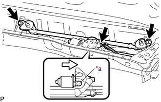
(b) Install the windshield wiper motor and link with the 2 bolts.
Torque:
5.5 N·m {56 kgf·cm, 49 in·lbf}
(c) Connect the connector.
3. INSTALL COWL TOP VENTILATOR LOUVER SUB-ASSEMBLY
(a) Engage the 9 guides to install the cowl top ventilator louver sub-assembly.
(b) Engage the guide and 6 claws.
4. INSTALL FRONT FENDER UPPER PROTECTOR LH
(a) Engage the 3 clips to install the front fender upper protector LH.
(b) Install the clip.
5. INSTALL FRONT FENDER UPPER PROTECTOR RH
HINT:
Use the same procedure as for the LH side.
6. INSTALL WINDSHIELD WIPER ARM AND BLADE ASSEMBLY LH
(a) When reusing the windshield wiper arm and blade assembly LH:
|
(1) Clean the wiper arm serrations to remove any burrs, dirt, etc. Text in Illustration
NOTICE: Do not grind down the wiper arm serrations. |
|
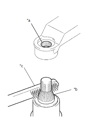
(2) Clean the wiper pivot serrations with a wire brush.
NOTICE:
Do not grind down the wiper pivot serrations.
(3) Operate the front wiper motor and then stop the front wiper motor in the automatic stop (park) position.
|
(b) Install the windshield wiper arm and blade assembly LH to the position with the nut as shown in the illustration. Torque: 22 N·m {224 kgf·cm, 16 ft·lbf} Text in Illustration
HINT: Hold the windshield wiper arm and blade assembly LH by hand while tightening the nut. |
|
.png)
(c) Operate the front wipers while spraying washer fluid on the windshield glass. Make sure that the front wipers function properly and there is no interference with the vehicle body.
(d) Check the automatic stop (park) position after lifting the wiper blade 2 times as shown in the illustration.
7. INSTALL WINDSHIELD WIPER ARM AND BLADE ASSEMBLY RH
(a) When reusing the windshield wiper arm and blade assembly RH:
|
(1) Clean the wiper arm serrations to remove any burrs, dirt, etc. Text in Illustration
NOTICE: Do not grind down the wiper arm serrations. |
|
(2) Clean the wiper pivot serrations with a wire brush.
NOTICE:
Do not grind down the wiper pivot serrations.
(3) Operate the front wiper motor and then stop the front wiper motor in the automatic stop (park) position.
|
(b) Install the windshield wiper arm and blade assembly RH to the position with the nut as shown in the illustration. Torque: 22 N·m {224 kgf·cm, 16 ft·lbf} Text in Illustration
HINT: Hold the windshield wiper arm and blade assembly RH by hand while tightening the nut. |
|
.png)
(c) Operate the front wipers while spraying washer fluid on the windshield glass. Make sure that the front wipers function properly and there is no interference with the vehicle body.
(d) Check the automatic stop (park) position after lifting the wiper blade 2 times as shown in the illustration.
8. INSTALL FRONT WIPER ARM HEAD CAP
(a) Engage the 3 claws to install the front wiper arm head cap.
HINT:
Use the same procedure for both sides.
 Inspection
INSPECTION
PROCEDURE
1. INSPECT WINDSHIELD WIPER MOTOR ASSEMBLY
(a) Check the LO operation.
Text in Illustration
*a
Component without harness connected
(Windshield Wipe ...
 Removal
REMOVAL
PROCEDURE
1. REMOVE FRONT WIPER ARM HEAD CAP
(a) Using a screwdriver with its tip wrapped in protective tape, disengage
the 3 claws to remove the front wiper arm head cap.
...
Other materials:
Operation Check
OPERATION CHECK
INPUT SIGNAL CHECK
*a
+RES
*b
-SET
*c
ON-OFF
*d
CANCEL
(a) Connect the Techstream to the DLC3.
(b) Check the cruise control main switch using the Data List functio ...
Lost Communication with ECM / PCM "A" (U0100,U0126,U0129,U0142)
DESCRIPTION
These DTCs are stored if there is a malfunction in the CAN communication system
connected to the blind spot monitor sensor.
HINT:
If CAN communication system DTCs are stored, they may also be stored for other
systems.
DTC Code
DTC Detection Condition
...
Installation
INSTALLATION
CAUTION / NOTICE / HINT
NOTICE:
When replacing the windshield glass of a vehicle equipped with a forward recognition
camera, make sure to use a Toyota genuine part. If a non-Toyota genuine part is
used, the forward recognition camera may not be able to be installed due to a missi ...
