Toyota Tacoma (2015-2018) Service Manual: Lost Communication with Alternator Missing Message (P161A87)
DESCRIPTION
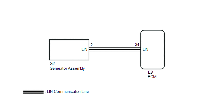
The ECM communicates with the generator assembly via LIN communication. If a LIN communication error is detected, the ECM stores this DTC.
|
DTC No. |
DTC Detection Condition |
Trouble Area |
|---|---|---|
|
P161A87 |
Generator assembly or ECM communication stop for about 17 minutes or more with the ignition switch ON. (1 trip detection logic) |
|
WIRING DIAGRAM
PROCEDURE
|
1. |
CHECK CHARGING SYSTEM |
(a) Check the charging system (See page .gif) ).
).
| NG | .gif) |
REPAIR OR REPLACE CHARGING SYSTEM |
|
.gif)
|
2. |
CHECK HARNESS AND CONNECTOR (ECM - GENERATOR ASSEMBLY) |
(a) Disconnect the E9 ECM connector.
(b) Disconnect the G2 generator assembly connector.
(c) Measure the resistance according to the value(s) in the table below.
Standard Resistance:
|
Tester Connection |
Condition |
Specified Condition |
|---|---|---|
|
E9-34 (LIN) - G2-2 (LIN) |
Always |
Below 1 Ω |
|
E9-34 (LIN) or G2-2 (LIN) - Body ground |
Always |
10 kΩ or higher |
| OK | |
REPLACE GENERATOR ASSEMBLY |
| NG | |
REPAIR OR REPLACE HARNESS OR CONNECTOR |
 On-vehicle Inspection
ON-VEHICLE INSPECTION
PROCEDURE
1. CHECK BATTERY CONDITION
NOTICE:
If the battery is weak or if the engine is difficult to start, recharge the battery
and perform inspections again before return ...
 Charging Failure
PROCEDURE
1.
CHECK GENERATOR PULLEY WITH CLUTCH (ON-VEHICLE INSPECTION)
(a) Start the engine and visually check if the fan of the generator rotor assembly
located i ...
Other materials:
Reassembly
REASSEMBLY
PROCEDURE
1. INSTALL COMPRESSOR PICK UP SENSOR
(a) Install the compressor pick up sensor with the 3 screws.
(b) Engage the clamp.
2. INSTALL MAGNET CLUTCH ASSEMBLY
(a) Secure the cooler compressor assembly in a vise between ...
Adjustment
ADJUSTMENT
PROCEDURE
1. PREPARE VEHICLE FOR FOG LIGHT AIMING ADJUSTMENT
(a) Prepare the vehicle:
HINT:
Ensure that there is no damage or deformation to the body around the
fog lights.
Fill the fuel tank.
Make sure that the oil is filled to the specified level.
Make sure ...
Inspection
INSPECTION
PROCEDURE
1. INSPECT HEADLIGHT DIMMER SWITCH ASSEMBLY
(a) Check the resistance.
(1) Measure the resistance according to the value(s) in the table below.
Text in Illustration
*a
Component without harness connected
(Headlight Dimme ...
