Toyota Tacoma (2015-2018) Service Manual: Removal
REMOVAL
PROCEDURE
1. REMOVE FRONT NO. 2 EXHAUST PIPE ASSEMBLY (for 2GR-FKS)
.gif)
2. REMOVE PROPELLER SHAFT HEAT INSULATOR BRACKET SUB-ASSEMBLY
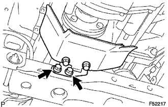
(a) Remove the 2 bolts and propeller shaft heat insulator bracket.
3. REMOVE FRONT PROPELLER SHAFT ASSEMBLY
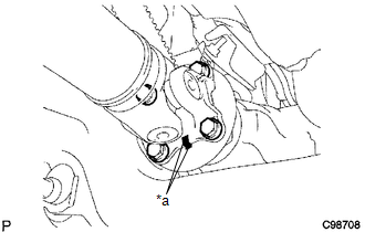
(a) Place matchmarks on the propeller shaft flange and differential flange.
Text in Illustration|
*a |
Matchmark |
(b) Remove the 4 nuts, 4 bolts, 4 washers and front propeller shaft.
|
(c) Place matchmarks on the propeller shaft flange and transfer flange. Text in Illustration
|
|
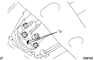
(d) Remove the 4 nuts, 4 washers and front propeller shaft.
 Components
COMPONENTS
ILLUSTRATION
...
 Disassembly
DISASSEMBLY
PROCEDURE
1. INSPECT FRONT PROPELLER SHAFT UNIVERSAL JOINT SPIDER BEARING
(a) Check the spider bearings for wear and damage.
(b) Check each spider bearing's axial play by turning t ...
Other materials:
4WD Control ECU Communication Stop Mode
DESCRIPTION
Detection Item
Symptom
Trouble Area
4WD Control ECU Communication Stop Mode
Either condition is met:
Communication stop for "Four Wheel Drive Control" is indicated
on the "Communication Bus C ...
Open in Bus 5 Main Bus Line
DESCRIPTION
There may be an open circuit in one of the CAN main bus lines when the resistance
between terminals 15 (CA5H) and 16 (CA5L) of the central gateway ECU (network gateway
ECU) is 70 Ω or higher.
Detection Item
Trouble Area
Resistance between ter ...
Detachable pole antenna
The antenna can be removed.
■ Removing the antenna
Place the included wrench around the antenna.
When not in use, the wrench is stored in glove box.
Loosen the antenna with the wrench and remove it.
■ Installing the antenna
Tighten the antenna by one hand until it will not t ...
