Toyota Tacoma (2015-2018) Service Manual: Disassembly
DISASSEMBLY
PROCEDURE
1. INSPECT FRONT PROPELLER SHAFT UNIVERSAL JOINT SPIDER BEARING
(a) Check the spider bearings for wear and damage.
(b) Check each spider bearing's axial play by turning the yoke while holding the shaft tightly.
Maximum bearing axial play:
0 to 0.05 mm (0 to 0.002 in.)
2. REMOVE FRONT PROPELLER SHAFT UNIVERSAL JOINT SPIDER BEARING
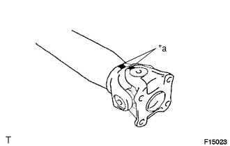
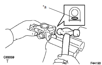
(a) Place matchmarks on the propeller shaft and flange yoke.
Text in Illustration|
*a |
Matchmark |
|
(b) Using a brass bar and a hammer, slightly tap in the spider bearing outer races. |
|
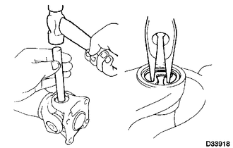
(c) Using needle-nose pliers, remove the 4 snap rings from the grooves.
|
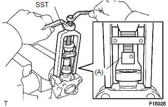
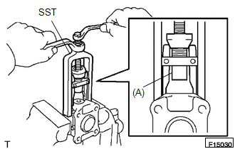
(d) Using SST, push the spider bearing out of the propeller shaft. SST: 09332-25010 HINT: Sufficiently raise the part indicated by (A) so that it does not come into contact with the spider bearing. |
|
|
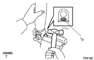
(e) Clamp the spider bearing outer race in a vise and tap off the propeller shaft with a hammer. HINT: Remove the bearing on the opposite side in the same procedure. Text in Illustration
NOTICE: Do not tap the shaft. |
|
|
(f) Install the 2 removed spider bearing outer races onto the spider, and clamp them in a vise. |
|
(g) Using SST, push the bearing out of the yoke.
SST: 09332-25010
HINT:
Sufficiently raise the part indicated by (A) so that it does not come into contact with the bearing.
|
(h) Clamp the outer bearing race in a vise and tap off the flange yoke with a hammer. Text in Illustration
|
|
(i) Remove the spider.
 Removal
REMOVAL
PROCEDURE
1. REMOVE FRONT NO. 2 EXHAUST PIPE ASSEMBLY (for 2GR-FKS)
2. REMOVE PROPELLER SHAFT HEAT INSULATOR BRACKET SUB-ASSEMBLY
(a) Remove the 2 bolts and propeller shaft heat insu ...
 Inspection
INSPECTION
PROCEDURE
1. INSPECT FRONT PROPELLER SHAFT ASSEMBLY
(a) Using a dial indicator, check the propeller shaft runout.
Maximum runout:
0.6 mm (0.024 in.)
If the shaft runout is greater ...
Other materials:
System Description
SYSTEM DESCRIPTION
1. FRONT SEAT HEATER
(a) By operating the seat heater switch on the air conditioning control assembly,
the temperature can be controlled within the range of 36 to 42.2°C (96 to 108°F).
(b) The on/off status and heater level of each seat heater are indicated by the
respect ...
Steering Angle Sensor Internal Circuit (C1433)
DESCRIPTION
The skid control ECU (brake actuator assembly) outputs this DTC when it receives
an internal malfunction signal from the steering angle sensor.
DTC No.
Detection Item
DTC Detection Condition
Trouble Area
C1433
St ...
Inspection
INSPECTION
PROCEDURE
1. INSPECT CYLINDER BLOCK FOR WARPAGE
(a) Using a precision straightedge and feeler gauge, measure the warpage
of the contact surface of the cylinder head gasket.
Standard warpage:
0 to 0.05 mm (0 to 0.00197 in.)
Maximum warpage:
0.07 mm (0.00276 ...
