Toyota Tacoma (2015-2018) Service Manual: Removal
REMOVAL
PROCEDURE
1. PRECAUTION
NOTICE:
After turning the ignition switch off, waiting time may be required before disconnecting the cable from the negative (-) battery terminal. Therefore, make sure to read the disconnecting the cable from the negative (-) battery terminal notices before proceeding with work.
Click here .gif)
2. DISCONNECT CABLE FROM NEGATIVE BATTERY TERMINAL
NOTICE:
When disconnecting the cable, some systems need to be initialized after the cable is reconnected.
Click here
3. REMOVE FRONT WHEELS
4. REMOVE NO. 2 ENGINE UNDER COVER SUB-ASSEMBLY (w/ Off Road Package)
5. REMOVE NO. 1 ENGINE UNDER COVER SUB-ASSEMBLY
6. DRAIN DIFFERENTIAL OIL
Click here
7. REMOVE FRONT PROPELLER SHAFT ASSEMBLY
Click here
8. REMOVE FRONT AXLE SHAFT LH NUT
Click here
9. REMOVE FRONT AXLE SHAFT RH NUT
HINT:
Use the same procedure as for the LH side.
10. SEPARATE FRONT STABILIZER LINK ASSEMBLY LH
Click here
11. SEPARATE FRONT STABILIZER LINK ASSEMBLY RH
HINT:
Use the same procedure as for the LH side.
12. SEPARATE FRONT SPEED SENSOR LH
Click here
13. SEPARATE FRONT SPEED SENSOR RH
HINT:
Use the same procedure as for the LH side.
14. SEPARATE TIE ROD END SUB-ASSEMBLY LH
Click here
15. SEPARATE TIE ROD END SUB-ASSEMBLY RH
HINT:
Use the same procedure as for the LH side.
16. SEPARATE FRONT SUSPENSION LOWER ARM LH
Click here
17. SEPARATE FRONT SUSPENSION LOWER ARM RH
HINT:
Use the same procedure as for the LH side.
18. REMOVE FRONT DRIVE SHAFT ASSEMBLY LH
Click here
19. REMOVE FRONT DRIVE SHAFT ASSEMBLY RH
HINT:
Use the same procedure as for the LH side.
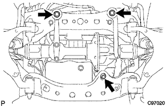
20. REMOVE FRONT DIFFERENTIAL CARRIER ASSEMBLY
(a) Remove the bolt and separate the front differential breather tube bracket.
(b) Support the front differential with a jack.
(c) Remove the front differential mount nut No. 1.
(d) Remove the 2 front mounting bolts and 2 nuts.
(e) Disconnect the actuator hose and connector.
(f) Disconnect the differential oil temperature sensor connector and clip.
(g) Remove the bolt and disconnect the bracket.
(h) Lower the jack and remove the front differential assembly.
(i) Remove the 2 bolts and No. 3 front differential support.
(j) Remove the 5 bolts and 2 front differential supports.
 Components
COMPONENTS
ILLUSTRATION
ILLUSTRATION
ILLUSTRATION
ILLUSTRATION
...
 Installation
INSTALLATION
PROCEDURE
1. INSTALL FRONT DIFFERENTIAL CARRIER ASSEMBLY
(a) Connect the actuator hose and connector.
(b) Install the No. 1 mounting support with the 3 bolts.
Torque:
186 N·m {1 ...
Other materials:
Precaution
PRECAUTION
1. IGNITION SWITCH EXPRESSION
(a) The type of ignition switch used on this model differs depending on the specifications
of the vehicle.
The expressions listed in the table below are used in this section.
Expression
Ignition Switch (Position)
Engine ...
Tire inflation pressure
■ Tire inflation pressure
The recommended cold tire inflation pressure and tire size is displayed on the
tire and loading information label.
Regular Cab and Double Cab models
Access Cab models
■ Inspection and adjustment procedure
1. Tire valve
2. Tire pressure gauge
Re ...
Reassembly
REASSEMBLY
PROCEDURE
1. INSTALL RADIATOR GRILLE MOULDING
(a) Engage the 8 claws to install the radiator grille moulding.
(b) Install the 8 screws.
2. INSTALL NO. 1 RADIATOR GRILLE GARNISH
(a) for Type A and Type B:
(1) Engag ...
