Toyota Tacoma (2015-2018) Service Manual: Reassembly
REASSEMBLY
CAUTION / NOTICE / HINT
HINT:
- Use the same procedures for both the LH and RH sides.
- The procedure described below is for the LH side.
PROCEDURE
1. INSTALL SIDE TURN SIGNAL LIGHT ASSEMBLY (w/ Side Turn Signal Light)
.gif)
2. INSTALL OUTER MIRROR COVER (w/o Side Turn Signal Light)
|
(a) Engage the 8 claws to install the outer mirror cover. |
|
.png)
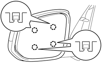
3. INSTALL OUTER MIRROR COVER (w/ Side Turn Signal Light)
|
(a) Engage the 7 claws to install the outer mirror cover. |
|
.png)
4. INSTALL OUTER MIRROR
|
(a) Connect the 3 connectors. |
|
.png)
(b) Engage the clamp.
|
(c) Engage the 4 claws to install the outer mirror. NOTICE: Be careful not to press the outer mirror with excessive force to prevent the glass from breaking. |
|
 Inspection
INSPECTION
PROCEDURE
1. INSPECT OUTER MIRROR LH
(a) Check the outer mirror heater operation.
Text in Illustration
*a
Component without harness con ...
 Installation
INSTALLATION
CAUTION / NOTICE / HINT
HINT:
Use the same procedures for both the LH and RH sides.
The procedure described below is for the LH side.
PROCEDURE
1. INSTALL OUTER REA ...
Other materials:
Adjustment
ADJUSTMENT
CAUTION / NOTICE / HINT
HINT:
Use the same procedures for both the LH and RH sides.
The procedure described below is for the LH side.
Centering bolts are used to mount the door hinge to the vehicle body
and door. The door cannot be adjusted with the centering bolts ...
System Description
SYSTEM DESCRIPTION
1. SEAT BELT WARNING SYSTEM DESCRIPTION
(a) Seat belt warning light operation for driver seat belt:
The seat belt warning light on the combination meter assembly illuminates, blinks
or turns off in accordance with the driver seat belt state, vehicle speed, shift
lever posit ...
Certification Ecu
Components
COMPONENTS
ILLUSTRATION
Installation
INSTALLATION
PROCEDURE
1. INSTALL CERTIFICATION ECU (SMART KEY ECU ASSEMBLY)
(a) Install the certification ECU (smart key ECU assembly) with the 2 nuts.
Torque:
6.5 N·m {66 kgf·cm, 58 in·lbf}
(b) Engage the clamp to install the wire ...
