Toyota Tacoma (2015-2018) Service Manual: Adjustment
ADJUSTMENT
CAUTION / NOTICE / HINT
HINT:
- Use the same procedures for both the LH and RH sides.
- The procedure described below is for the LH side.
- Centering bolts are used to mount the door hinge to the vehicle body and door. The door cannot be adjusted with the centering bolts on. Substitute the centering bolts for standard bolts when making adjustments.
- A bolt without a torque specification is shown in the standard bolt
chart (See page
.gif) ).
).
PROCEDURE
1. INSPECT FRONT DOOR PANEL SUB-ASSEMBLY (for Double Cab)
(a) Check that the clearance measurements of areas "A" through "J" are within each standard range.
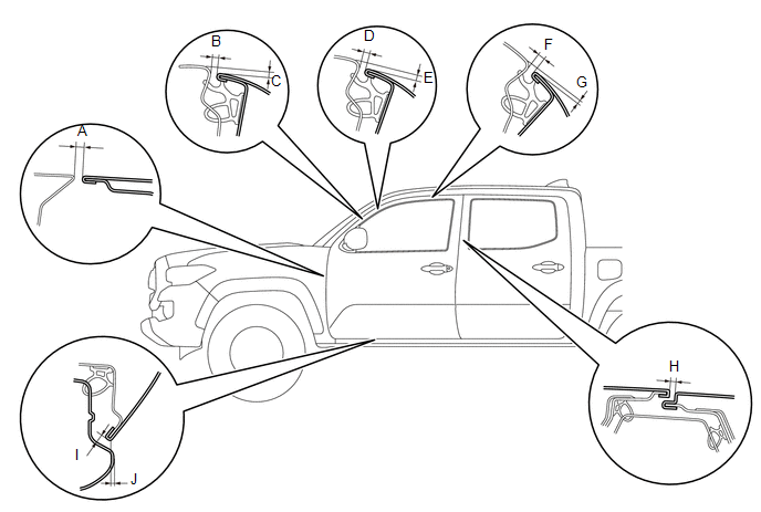 Standard:
|
Area |
Measurement |
Area |
Measurement |
|
A |
3.2 to 6.2 mm (0.126 to 0.244 in.) |
B |
3.4 to 6.4 mm (0.134 to 0.252 in.) |
|
C |
1.1 to 4.1 mm (0.043 to 0.161 in.) |
D |
3.3 to 6.3 mm (0.130 to 0.248 in.) |
|
E |
1.1 to 4.1 mm (0.043 to 0.161 in.) |
F |
3.3 to 6.3 mm (0.130 to 0.248 in.) |
|
G |
0.7 to 3.7 mm (0.028 to 0.146 in.) |
H |
3.5 to 6.5 mm (0.138 to 0.256 in.) |
|
I |
3.5 to 6.5 mm (0.138 to 0.256 in.) |
J |
0.5 to 3.5 mm (0.020 to 0.138 in.) |
2. INSPECT FRONT DOOR PANEL SUB-ASSEMBLY (for Access Cab)
(a) Check that the clearance measurements of areas "A" through "J" are within each standard range.
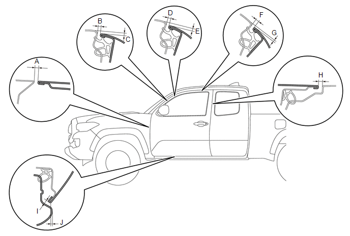 Standard:
|
Area |
Measurement |
Area |
Measurement |
|
A |
3.2 to 6.2 mm (0.126 to 0.244 in.) |
B |
3.4 to 6.4 mm (0.134 to 0.252 in.) |
|
C |
1.1 to 4.1 mm (0.043 to 0.161 in.) |
D |
3.3 to 6.3 mm (0.130 to 0.248 in.) |
|
E |
1.1 to 4.1 mm (0.043 to 0.161 in.) |
F |
3.3 to 6.3 mm (0.130 to 0.248 in.) |
|
G |
0.7 to 3.7 mm (0.028 to 0.146 in.) |
H |
4.5 to 7.5 mm (0.177 to 0.295 in.) |
|
I |
3.5 to 6.5 mm (0.138 to 0.256 in.) |
J |
0.5 to 3.5 mm (0.020 to 0.138 in.) |
3. ADJUST FRONT DOOR PANEL SUB-ASSEMBLY
(a) Apply strips of protective tape to the door panel and fender panel, as shown in the illustration.
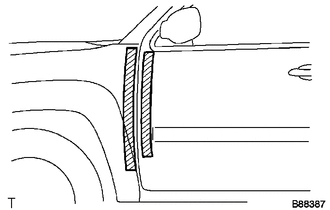 Text in Illustration
.png) |
Protective Tape |
|
(b) Open the door, and then disengage the 3 clips. HINT: If any clips are damaged, replace them with new ones. |
|
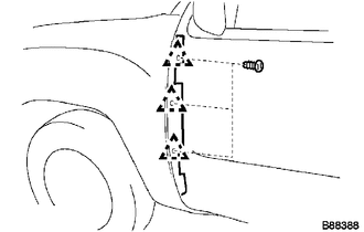
(c) Remove the front fender side panel protector LH from the gap between the fender and door.
|
(d) Using SST, adjust the door horizontally and vertically by loosening the body side hinge bolts. SST: 09812-00010 |
|
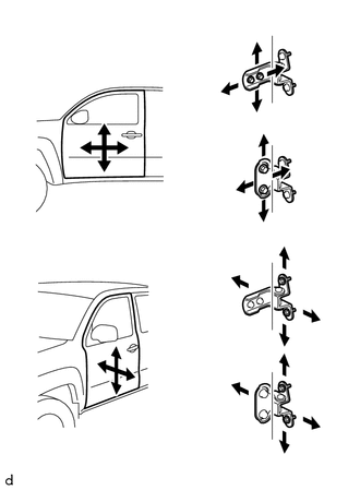
(e) Tighten the body side hinge bolts after the adjustment.
Torque:
26 N·m {265 kgf·cm, 19 ft·lbf}
(f) Horizontally and vertically adjust the door by loosening the door side hinge bolts.
(g) Tighten the door side hinge bolts after the adjustment.
Torque:
26 N·m {265 kgf·cm, 19 ft·lbf}
|
(h) Adjust the striker position by slightly loosening the striker mounting screws with a T40 "TORX" socket wrench and hitting the striker with a plastic hammer. |
|
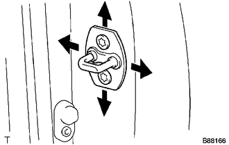
(i) Using a T40 "TORX" socket wrench, tighten the striker mounting screws after the adjustment.
Torque:
23 N·m {235 kgf·cm, 17 ft·lbf}
|
(j) Install the front fender side panel protector LH with the 3 clips. |
|
 Front Door
...
 Components
COMPONENTS
ILLUSTRATION
*1
FRONT ARMREST BASE UPPER PANEL SUB-ASSEMBLY
*2
FRONT DOOR GLASS INNER WEATHERSTRIP
*3
FRONT DOOR ...
Other materials:
Precaution
PRECAUTION
1. IGNITION SWITCH EXPRESSION
(a) The type of ignition switch used on this model differs depending on the specifications
of the vehicle. The expressions listed in the table below are used in this section.
Expression
Ignition Switch (Position)
Engine S ...
Data List / Active Test
DATA LIST / ACTIVE TEST
1. READ DATA LIST
HINT:
Using the Techstream to read the Data List allows the values or states of switches,
sensors, actuators and other items to be read without removing any parts. This non-intrusive
inspection can be very useful because intermittent conditions or sig ...
Inspection
INSPECTION
PROCEDURE
1. INSPECT COUNTER GEAR
(a) Using a dial indicator and 2 V-blocks, measure the counter gear runout.
Maximum runout:
0.03 mm (0.00118 in.)
If the runout is more than the maximum, replace the counter gear.
HINT:
Measure the 3 areas shown in the illust ...
