Toyota Tacoma (2015-2018) Service Manual: Certification Ecu
Components
COMPONENTS
ILLUSTRATION
Installation
INSTALLATION
PROCEDURE
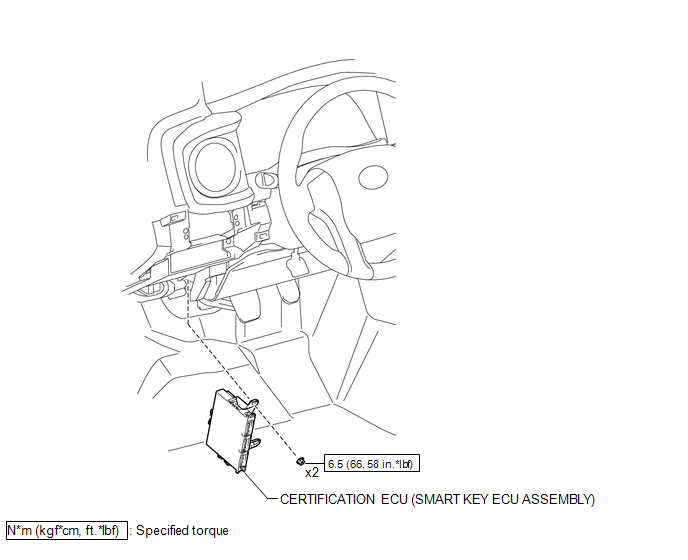
1. INSTALL CERTIFICATION ECU (SMART KEY ECU ASSEMBLY)
(a) Install the certification ECU (smart key ECU assembly) with the 2 nuts.
Torque:
6.5 N·m {66 kgf·cm, 58 in·lbf}
(b) Engage the clamp to install the wire harness.
(c) Connect the 3 connectors.
2. INSTALL INSTRUMENT PANEL LOWER FINISH PANEL SUB-ASSEMBLY
(See page .gif) )
)
Removal
REMOVAL
PROCEDURE
1. REMOVE INSTRUMENT PANEL LOWER FINISH PANEL SUB-ASSEMBLY
(See page .gif) )
)
2. REMOVE CERTIFICATION ECU (SMART KEY ECU ASSEMBLY)
|
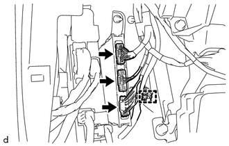
(a) Disconnect the 3 connectors. |
|
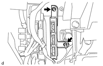
(b) Disengage the clamp to separate the wire harness.
|
(c) Remove the 2 nuts and certification ECU (smart key ECU assembly). |
|


Other materials:
Diagnostic Trouble Code Chart
DIAGNOSTIC TROUBLE CODE CHART
HINT:
If a trouble code is stored during the DTC check, inspect the trouble areas listed
for that code. For details of the code, refer to "See page" below.
Transponder Key ECU Assembly
DTC Code
Detection Item
See page
...
Disassembly
DISASSEMBLY
CAUTION / NOTICE / HINT
HINT:
Use the same procedure for the RH side and LH side.
The following procedure is for the LH side.
When removing the No. 2 front wheel opening extension pad or No. 1 front
wheel opening extension pad or front wheel opening extension pad, ...
Rear Center Seat Outer Belt Assembly(for Double Cab)
Components
COMPONENTS
ILLUSTRATION
Removal
REMOVAL
PROCEDURE
1. REMOVE REAR SEATBACK HINGE COVER
2. REMOVE REAR SEATBACK BOARD SUB-ASSEMBLY
3. REMOVE SEAT BELT ANCHOR COVER CAP
4. REMOVE REAR SEAT SHOULDER BELT COVER
5. REMOVE CENTER SEATBACK PAD
(a) Remove th ...
