Toyota Tacoma (2015-2018) Service Manual: Purge Valve
Components
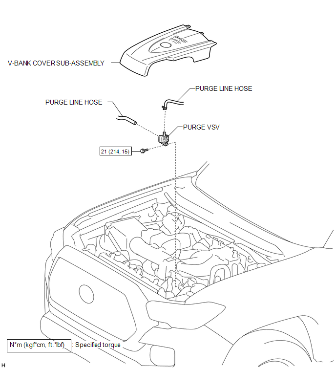
COMPONENTS
ILLUSTRATION
Inspection
INSPECTION
PROCEDURE
1. INSPECT PURGE VSV
|
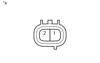
(a) Measure the resistance according to the value(s) in the table below. Text in Illustration
Standard Resistance:
If the result is not as specified, replace the purge VSV. |
|
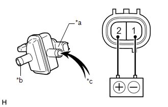
(b) Check the operation of the purge VSV.
|
(1) Apply battery voltage between the terminals of the purge VSV and check that the following occurs when blowing air into the port (E). Text in Illustration
OK:
If the result is not as specified, replace the purge VSV. |
|
Removal
REMOVAL
PROCEDURE
1. REMOVE V-BANK COVER SUB-ASSEMBLY
.gif)
2. REMOVE PURGE VSV
|
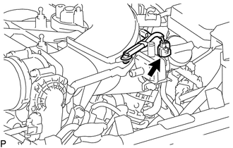
(a) Slide the hose clip and disconnect the purge line hose from the purge VSV. |
|
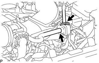
(b) Disconnect the purge line hose from the purge VSV.
|
(c) Disconnect the connector from the purge VSV. |
|
|
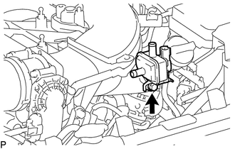
(d) Remove the bolt and purge VSV from the intake air surge tank. |
|
Installation
INSTALLATION
PROCEDURE
1. INSTALL PURGE VSV
(a) Install the purge VSV to the intake air surge tank with the bolt.
Torque:
21 N·m {214 kgf·cm, 15 ft·lbf}
(b) Connect the purge line hose to the purge VSV, and slide the hose clip to secure it.
(c) Connect the purge line hose to the purge VSV.
(d) Connect the connector to the purge VSV.
2. INSTALL V-BANK COVER SUB-ASSEMBLY
.gif)
 Pcv Valve
Components
COMPONENTS
ILLUSTRATION
Inspection
INSPECTION
PROCEDURE
1. INSPECT PCV VALVE SUB-ASSEMBLY
(a) Install a clean hose to the PCV valve sub-assembly.
(b) Check the PCV valve sub-a ...

Other materials:
Cruise Control Input Circuit (P0575)
DESCRIPTION
This DTC is stored when there is a malfunction in the ECM.
DTC No.
Detection Item
DTC Detection Condition
Trouble Area
P0575
Cruise Control Input Circuit
Either of the following conditions is met:
...
Cautions & Notices
CAUTION
This is a warning against anything which may cause injury to people if the
warning is ignored. You are informed about what you must or must not do in order
to reduce the risk of injury to yourself and others.
NOTICE
This is a warning against anything which may cause damage to the vehi ...
Air Mix Damper Control Servo Motor Circuit (Passenger Side) (B1441/41)
DESCRIPTION
This No. 2 air conditioning radiator damper servo sub-assembly (for front passenger
side air mix) is controlled by the air conditioning amplifier assembly and moves
the air mix damper (for front passenger side) to the desired position.
DTC No.
DTC Detection Co ...
