Toyota Tacoma (2015-2018) Service Manual: Ptc Heater Assembly
Components
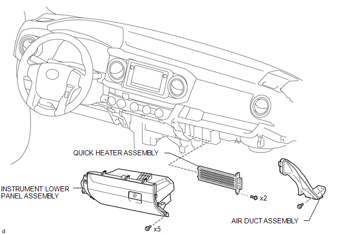
COMPONENTS
ILLUSTRATION
Removal
REMOVAL
PROCEDURE
1. REMOVE LOWER NO. 2 INSTRUMENT PANEL AIRBAG ASSEMBLY
(See page .gif) )
)
2. REMOVE INSTRUMENT LOWER PANEL ASSEMBLY
3. REMOVE AIR DUCT ASSEMBLY
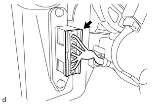
4. REMOVE QUICK HEATER ASSEMBLY
|
(a) Disconnect the connector. |
|
|
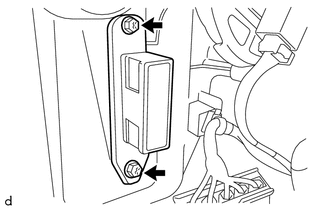
(b) Remove the 2 screws and quick heater assembly. |
|
Inspection
INSPECTION
PROCEDURE
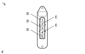
1. INSPECT QUICK HEATER ASSEMBLY
(a) Check the resistance.
|
(1) Measure the resistance according to the value(s) in the table below. Text in Illustration
Standard Resistance:
If the specified condition is not met, replace the quick heater assembly. |
|
Installation
INSTALLATION
PROCEDURE
1. INSTALL QUICK HEATER ASSEMBLY
(a) Install the quick heater assembly with the 2 screws.
(b) Connect the connector.
2. INSTALL AIR DUCT ASSEMBLY
.gif)
3. INSTALL INSTRUMENT LOWER PANEL ASSEMBLY
4. INSTALL LOWER NO. 2 INSTRUMENT PANEL AIRBAG ASSEMBLY
(See page )
 Magnetic Clutch Relay
Inspection
INSPECTION
PROCEDURE
1. INSPECT MAGNET-CLUTCH RELAY
(a) Check the resistance.
(1) Using an ohmmeter, measure the resistance between the terminals.
Standard:
...
 Ptc Heater Relay
Components
COMPONENTS
ILLUSTRATION
Inspection
INSPECTION
PROCEDURE
1. INSPECT PTC HEATER RELAY
(a) Check the resistance.
(1) Measure the resistance according to the value(s) i ...
Other materials:
Certification ECU Communication Stop Mode
DESCRIPTION
Detection Item
Symptom
Trouble Area
Certification ECU Communication Stop Mode
Either condition is met:
Communication stop for "Certification (Smart)" is indicated
on the "Communication Bus Ch ...
Distance Control Switch Circuit
DESCRIPTION
The distance control switch is used to set the distance for vehicle-to-vehicle
distance control mode. The distance control switch is installed in the steering
pad switch assembly. The vehicle-to-vehicle distance set value can be changed by
operating the steering pad switch assembl ...
Speed Sensor
Components
COMPONENTS
ILLUSTRATION
Removal
REMOVAL
PROCEDURE
1. REMOVE TRANSMISSION REVOLUTION SENSOR (NT)
(a) Disconnect the transmission revolution sensor (NT) connector.
(b) Remove the bolt and transmission revolution sensor (NT). ...
