Toyota Tacoma (2015-2018) Service Manual: Fuel Main Valve
Components
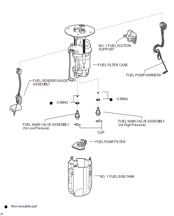
COMPONENTS
ILLUSTRATION
Removal
REMOVAL
PROCEDURE
1. REMOVE FUEL SUCTION TUBE WITH PUMP AND GAUGE ASSEMBLY
(See page .gif) )
)
2. REMOVE FUEL SENDER GAUGE ASSEMBLY
3. REMOVE NO. 1 FUEL SUB-TANK
4. REMOVE FUEL PUMP FILTER
5. REMOVE FUEL MAIN VALVE ASSEMBLY
(a) Remove the fuel main valve assembly (for High Pressure).
|
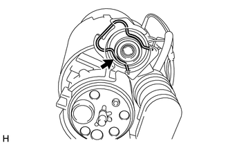
(1) Remove the clip from the fuel filter case. |
|
|
(2) Using a screwdriver, remove the fuel main valve assembly from the fuel filter case. NOTICE: Do not damage the fuel filter case. |
|

(3) Remove the 2 O-rings from the fuel main valve assembly.
(b) Remove the fuel main valve assembly (for Low Pressure).
|
(1) Remove the clip from the fuel filter case. |
|

|
(2) Using a screwdriver, remove the fuel main valve assembly from the fuel filter case. NOTICE: Do not damage the fuel filter case. |
|

(3) Remove the 2 O-rings from the fuel main valve assembly.
Installation
INSTALLATION
PROCEDURE
1. INSTALL FUEL MAIN VALVE ASSEMBLY
(a) Apply gasoline to 2 new O-rings. Then install the 2 O-rings to the fuel main valve assembly (for Low Pressure).
(b) Apply gasoline to 2 new O-rings. Then install the 2 O-rings to the fuel main valve assembly (for High Pressure).
(c) Install the 2 fuel main valve assemblies to the fuel filter case.
NOTICE:
- When installing the O-rings, make sure they do not become pinched or cut.
- The fuel main valve assembly (for Low Pressure) and fuel main valve assembly (for High Pressure) have identification marks (part numbers). If the parts are installed in the wrong location, the engine may stall. Therefore, make sure to install the parts in the correct location.
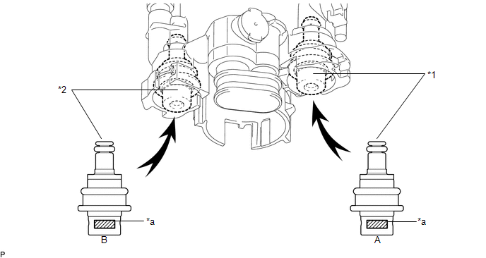 Text in Illustration
|
*1 |
Fuel Main Valve Assembly (for Low Pressure) |
*2 |
Fuel Main Valve Assembly (for High Pressure) |
|
*a |
Identification Mark (Part Number) |
- |
- |
|
A |
Fuel Main Valve Assembly (for Low Pressure) |
23070-31*** |
|
B |
Fuel Main Valve Assembly (for High Pressure) |
23070-36*** |
(d) Install the 2 clips to the fuel filter case.
2. INSTALL FUEL PUMP FILTER
.gif)
3. INSTALL NO. 1 FUEL SUB-TANK
4. INSTALL FUEL SENDER GAUGE ASSEMBLY
5. INSTALL FUEL SUCTION TUBE WITH PUMP AND GAUGE ASSEMBLY
 Installation
INSTALLATION
CAUTION / NOTICE / HINT
HINT:
Perform "Inspection After Repairs" after replacing the fuel injector assembly
(See page ).
PROCEDURE
1. INSTALL FUEL INJECTOR ASSEMBLY
HIN ...
 Fuel Pressure Sensor
Components
COMPONENTS
ILLUSTRATION
Inspection
INSPECTION
PROCEDURE
1. INSPECT FUEL DELIVERY PIPE SUB-ASSEMBLY (FUEL PRESSURE SENSOR)
NOTICE:
Do not remove the fuel pressure senso ...
Other materials:
Stop Light Relay Circuit (C1A4B)
DESCRIPTION
The skid control ECU (master cylinder solenoid)*1 or skid control ECU (brake
actuator assembly)*2 sends a stop light operation request signal to the stop light
relay (stop light switch assembly). If the skid control ECU (master cylinder solenoid)*1
or skid control ECU (brake actua ...
Output Speed Sensor Circuit No Signal (P0722,P077C,P077D)
DESCRIPTION
This sensor detects the rotation speed of the transmission output shaft and sends
signals to the ECM. By comparing the input turbine speed signal (NT) with the output
shaft speed sensor signal (SP2), the ECM detects the shift timing of the gears and
appropriately controls the engi ...
Cleaning and protecting the vehicle interior
The following procedures will help protect your vehicle’s interior and keep
it in top condition:
■ Protecting the vehicle interior
Remove dirt and dust using a vacuum cleaner. Wipe dirty surfaces with a cloth
dampened with lukewarm water.
■ Cleaning the leather areas
● Re ...
