Toyota Tacoma (2015-2018) Service Manual: Open or Short in Rear Speed Sensor RH Circuit (C1407,C1408)
DESCRIPTION
Refer to DTCs C1401 and C1402 (See page .gif) ).
).
|
DTC Code |
DTC Detection Condition |
Trouble Area |
|---|---|---|
|
C1407 C1408 |
Either condition is met:
|
|
HINT:
- DTC C1407 is for the rear speed sensor RH.
- DTC C1408 is for the rear speed sensor LH.
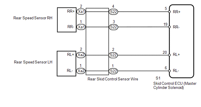
WIRING DIAGRAM
CAUTION / NOTICE / HINT
NOTICE:
- When replacing the skid control ECU (master cylinder solenoid), perform
calibration (See page
).
- Check the speed sensor signal after replacement (See page
).
PROCEDURE
|
1. |
CHECK HARNESS AND CONNECTOR (MOMENTARY INTERRUPTION) |
(a) Using the Techstream, check for any momentary interruption in the wire harness
and connector corresponding to the DTC (See page
).
|
Tester Display |
Measurement Item/Range |
Normal Condition |
Diagnostic Note |
|---|---|---|---|
|
RR Speed Open |
Rear speed sensor RH open detection/ Error or Normal |
Normal |
- |
|
RL Speed Open |
Rear speed sensor LH open detection/ Error or Normal |
Normal |
- |
OK:
Normal (there are no momentary interruptions).
HINT:
Perform the above inspection before removing the sensor and connector.
| NG | .gif) |
GO TO STEP 4 |
|
.gif)
|
2. |
READ VALUE USING TECHSTREAM (REAR SPEED SENSOR) |
| NG | |
GO TO STEP 4 |
|
|
3. |
RECONFIRM DTC |
(a) Clear the DTCs (See page
).
(b) Turn the ignition switch off.
(c) Start the engine.
(d) Drive the vehicle at a speed of 40 km/h (25 mph) or more for at least 60 seconds.
(e) Check if the same DTC is output (See page
).
|
Result |
Proceed to |
|---|---|
|
DTCs C1407 and C1408 are not output |
A |
|
DTCs C1407 and/or C1408 are output |
B |
| A | |
USE SIMULATION METHOD TO CHECK |
| B | |
REPLACE MASTER CYLINDER SOLENOID |
|
4. |
INSPECT SKID CONTROL SENSOR WIRE |
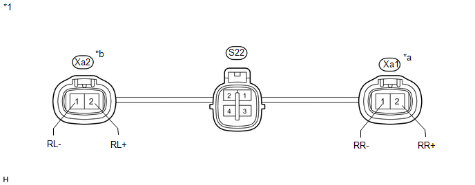 Text in Illustration
|
*1 |
Skid Control Sensor Wire |
- |
- |
|
*a |
RH |
*b |
LH |
(a) Remove the skid control sensor wire.
(b) Measure the resistance according to the value(s) in the table below.
Standard Resistance:
RH|
Tester Connection |
Condition |
Specified Condition |
|---|---|---|
|
S22-4 - Xa1-2 (RR+) |
Always |
Below 1 Ω |
|
S22-3 - Xa1-1 (RR-) |
Always |
Below 1 Ω |
|
S22-4 - S22-3 |
Always |
10 kΩ or higher |
|
S22-4 - S22-1 |
Always |
10 kΩ or higher |
|
S22-4 - S22-2 |
Always |
10 kΩ or higher |
|
Tester Connection |
Condition |
Specified Condition |
|---|---|---|
|
S22-2 - Xa2-2 (RL+) |
Always |
Below 1 Ω |
|
S22-1 - Xa2-1 (RL-) |
Always |
Below 1 Ω |
|
S22-2 - S22-1 |
Always |
10 kΩ or higher |
|
S22-2 - S22-3 |
Always |
10 kΩ or higher |
|
S22-2 - S22-4 |
Always |
10 kΩ or higher |
| NG | |
REPLACE SKID CONTROL SENSOR WIRE |
|
|
5. |
CHECK HARNESS AND CONNECTOR (SKID CONTROL ECU - REAR SPEED SENSOR) |
(a) Install the skid control sensor wire.
(b) Disconnect the S1 skid control ECU (master cylinder solenoid) connector.
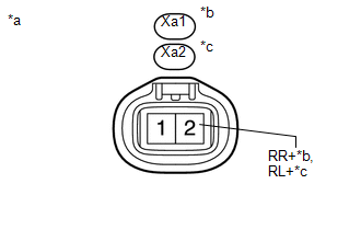
(c) Disconnect the Xa1 and/or Xa2 rear speed sensor connector.
(d) Measure the resistance according to the value(s) in the table below.
Standard Resistance:
RH|
Tester Connection |
Condition |
Specified Condition |
|---|---|---|
|
S1-5 (RR+) - Xa1-2 (RR+) |
Always |
Below 1 Ω |
|
S1-5 (RR+) - Body ground |
Always |
10 kΩ or higher |
|
S1-19 (RR-) - Xa1-1 (RR-) |
Always |
Below 1 Ω |
|
S1-19 (RR-) - Body ground |
Always |
10 kΩ or higher |
|
Tester Connection |
Condition |
Specified Condition |
|---|---|---|
|
S1-20 (RL+) - Xa2-2 (RL+) |
Always |
Below 1 Ω |
|
S1-20 (RL+) - Body ground |
Always |
10 kΩ or higher |
|
S1-6 (RL-) - Xa2-1 (RL-) |
Always |
Below 1 Ω |
|
S1-6 (RL-) - Body ground |
Always |
10 kΩ or higher |
| NG | |
REPAIR OR REPLACE HARNESS OR CONNECTOR |
|
|
6. |
INSPECT SKID CONTROL ECU (RR+, RL+ TERMINAL) |
(a) Disconnect the Xa1 and/or Xa2 rear speed sensor connector.
(b) Connect the S1 skid control ECU (master cylinder solenoid) connector.
|
(c) Measure the voltage according to the value(s) in the table below. Standard Voltage: RH
|
|
| OK | |
REPLACE REAR SPEED SENSOR |
| NG | |
REPLACE MASTER CYLINDER SOLENOID |
 Open or Short in Front Speed Sensor RH Circuit (C1405,C1406)
DESCRIPTION
Refer to DTCs C1401 and C1402 (See page ).
DTC Code
DTC Detection Condition
Trouble Area
C1405
C1406
Either condition is ...
 Front Speed Sensor RH Performance (C1409,C1410)
DESCRIPTION
Refer to DTCs C1401 and C1402 (See page ).
DTC Code
DTC Detection Condition
Trouble Area
C1409
C1410
One of the following ...
Other materials:
Reassembly
REASSEMBLY
PROCEDURE
1. INSTALL REAR BUMPER SIDE STAY LH
(a) Install the rear bumper side stay LH with the 2 bolts.
Torque:
30 N·m {306 kgf·cm, 22 ft·lbf}
2. INSTALL REAR BUMPER SIDE STAY RH
HINT:
Use the same procedure as for ...
Lost Communication with Alternator Missing Message (P161A87)
DESCRIPTION
The ECM communicates with the generator assembly via LIN communication. If a
LIN communication error is detected, the ECM stores this DTC.
DTC No.
DTC Detection Condition
Trouble Area
P161A87
Generator assembly or ECM commu ...
Microphone Circuit between Microphone and Radio Receiver
DESCRIPTION
The navigation receiver assembly and telephone microphone assembly are connected
to each other using the microphone connection detection signal lines.
Using this circuit, the navigation receiver assembly sends power to the telephone
microphone assembly and the telephone microphone ...
