Toyota Tacoma (2015-2018) Service Manual: On-vehicle Inspection
ON-VEHICLE INSPECTION
PROCEDURE
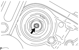
1. INSPECT CAMSHAFT TIMING GEAR BOLT
(a) Remove the camshaft timing oil control solenoid assembly (See page
.gif) ).
).
|
(b) Check that the plunger strokes when the plunger in the center of the camshaft timing gear bolt is pressed. Standard stroke: 4.5 mm (0.177 in.) or more HINT: When pressing the plunger, there is a stepped feeling but this is not a malfunction. If the result is not as specified, replace the camshaft timing gear bolt. |
|
(c) Install the camshaft timing oil control solenoid assembly (See page
).
 Components
COMPONENTS
ILLUSTRATION
...
 Removal
REMOVAL
CAUTION / NOTICE / HINT
NOTICE:
If one of the camshaft timing gear bolts is already removed, do not remove any
other camshaft timing gear bolts.
PROCEDURE
1. REMOVE NO. 2 ENGINE UNDER C ...
Other materials:
Components
COMPONENTS
ILLUSTRATION
*A
w/ Rear Seat Assembly
*B
w/o Rear Seat Assembly
*1
BACK PANEL GARNISH HOLE PLUG
*2
BACK PANEL TRIM
*3
NO. 3 ROOM PARTITION COVER
*4
...
Driver Side Power Window does not Operate with Power Window Master Switch
DESCRIPTION
When the engine is running or the ignition switch is ON, the front power window
regulator motor assembly LH is operated by the power window regulator master switch
assembly. The front power window regulator motor assembly LH has motor, regulator,
and ECU functions.
HINT:
If the ...
System Diagram
SYSTEM DIAGRAM
Communication Table
Sender
Receiver
Signal
Line
ECM
Millimeter Wave Radar Sensor Assembly
Cruise control operation signal
Accelerator pedal idle position signal
Accel overr ...
