Toyota Tacoma (2015-2018) Service Manual: Noise Filter(for 2tr-fe)
Components
COMPONENTS
ILLUSTRATION
.png)
Removal
REMOVAL
PROCEDURE
1. DISCONNECT CABLE FROM NEGATIVE BATTERY TERMINAL
2. REMOVE AIR CLEANER ASSEMBLY
(See page .gif) )
)
3. REMOVE RADIO SETTING CONDENSER
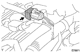
(a) Disconnect the connector.
(b) Remove the tape and the radio setting condenser.
Installation
INSTALLATION
PROCEDURE
1. INSTALL RADIO SETTING CONDENSER
.png)
(a) Connect the connector.
(b) Wind new vinyl tape around the hose and install the radio setting condenser.
2. INSTALL AIR CLEANER ASSEMBLY
(See page .gif) )
)
3. CONNECT CABLE TO NEGATIVE BATTERY TERMINAL
Torque:
5.4 N·m {55 kgf·cm, 48 in·lbf}
 Noise Filter(for 2gr-fks)
Components
COMPONENTS
ILLUSTRATION
Removal
REMOVAL
PROCEDURE
1. DISCONNECT CABLE FROM NEGATIVE BATTERY TERMINAL
2. REMOVE V-BANK COVER
(See page )
3. REMOVE AIR CLEANER ASSEMBLY
(See ...
 Radio Antenna
Components
COMPONENTS
ILLUSTRATION
Removal
REMOVAL
PROCEDURE
1. REMOVE ROOF HEADLINING ASSEMBLY (for Double Cab)
(See page )
2. REMOVE ROOF HEADLINING ASSEMBLY (for Access Cab)
(See p ...
Other materials:
Front Left Seat Heat Sensor Circuit (B14C1)
DESCRIPTION
Output to the front seat cushion heater assembly LH temperature sensor stops
if one of the following occurs: 1) the temperature sensor is open or shorted; or
2) the temperature sensor is damaged and its output value does not change.
DTC Code
DTC Detection Cond ...
Data List / Active Test
DATA LIST / ACTIVE TEST
1. DATA LIST
NOTICE:
In the table below, the values listed under "Normal Condition" are reference
values. Do not depend solely on these reference values when deciding whether a part
is faulty or not.
HINT:
Using the Techstream to read the Data List allows t ...
Diagnostic Trouble Code Chart
DIAGNOSTIC TROUBLE CODE CHART
HINT:
If a trouble code is displayed during the DTC check, inspect the trouble area
for that code. For details of each code, refer to the relevant page listed under
respective "See page" in the DTC chart.
Tire Pressure Warning ECU and Receiver
...
