Toyota Tacoma (2015-2018) Service Manual: Master Cylinder Pressure Sensor Zero Point High Malfunction (C1422)
DESCRIPTION
|
DTC No. |
Detection Item |
DTC Detection Condition |
Trouble Area |
|---|---|---|---|
|
C1422 |
Master Cylinder Pressure Sensor Zero Point High Malfunction |
When vehicle speed is 3 km/h (2 mph) or more and stop light switch assembly is OFF, master cylinder pressure continuously exceeds 1.764 MPa (18.0 kgf/cm2, 255 psi) for 5 seconds or more. |
|
WIRING DIAGRAM
Refer to DTC C1380 (See page .gif) ).
).
CAUTION / NOTICE / HINT
NOTICE:
- When replacing the skid control ECU (brake actuator assembly), perform
zero point calibration and store system information (See page
).
- Inspect the fuses for circuits related to this system before performing the following inspection procedure.
PROCEDURE
|
1. |
CHECK DTC |
(a) Clear the DTCs (See page
).
(b) Turn the ignition switch off.
(c) Start the engine.
(d) Perform a road test.
(e) Check for DTCs (See page
).
|
Result |
Proceed to |
|---|---|
|
DTC C1422 is output |
A |
|
DTCs C1422 and C1380 are output |
B |
|
DTCs C1422 and C1425 are output |
C |
| B | .gif) |
GO TO DIAGNOSTIC TROUBLE CODE CHART |
| C | |
GO TO DIAGNOSTIC TROUBLE CODE CHART |
|
.gif)
|
2. |
READ VALUE USING TECHSTREAM (STOP LIGHT SWITCH ASSEMBLY) |
(a) Connect the Techstream to the DLC3.
(b) Turn the ignition switch to ON.
(c) Turn the Techstream on.
(d) Enter the following menus: Chassis / ABS/VSC/TRAC / Data List.
(e) In accordance with the display on the Techstream, read the Data List.
ABS/VSC/TRAC|
Tester Display |
Measurement Item |
Range |
Normal Condition |
Diagnostic Note |
|---|---|---|---|---|
|
Stop Light SW |
Stop light switch assembly |
ON or OFF |
OFF: Brake pedal released ON: Brake pedal depressed |
- |
(f) Check that the stop light switch assembly condition observed on the Techstream changes according to brake pedal operation.
OK:
The Techstream displays ON or OFF according to brake pedal operation.
| NG | |
GO TO STEP 5 |
|
|
3. |
READ VALUE USING TECHSTREAM (MASTER CYLINDER PRESSURE SENSOR) |
(a) Connect the Techstream to the DLC3.
(b) Turn the ignition switch to ON.
(c) Turn the Techstream on.
(d) Enter the following menus: Chassis / ABS/VSC/TRAC / Data List.
(e) In accordance with the display on the Techstream, read the Data List.
ABS/VSC/TRAC|
Tester Display |
Measurement Item |
Range |
Normal Condition |
Diagnostic Note |
|---|---|---|---|---|
|
Master Cylinder Pressure |
Master cylinder pressure sensor pressure |
Min.: 0.00 MPa Max.: 23.28 MPa |
Brake pedal operated: Proportional to pedal force Brake Brake pedal released: 0.00 to 1.76 MPa |
- |
OK:
Data List pressure is within standard range.
| NG | |
REPLACE BRAKE ACTUATOR ASSEMBLY |
|
|
4. |
RECONFIRM DTC |
(a) Clear the DTCs (See page
).
(b) Turn the ignition switch off.
(c) Start the engine.
(d) Perform a road test.
(e) Check if the same DTC is recorded (See page
).
|
Result |
Proceed to |
|---|---|
|
DTC C1422 is not output |
A |
|
DTC C1422 is output |
B |
| A | |
USE SIMULATION METHOD TO CHECK |
| B | |
REPLACE BRAKE ACTUATOR ASSEMBLY |
|
5. |
CHECK BRAKE PEDAL AND STOP LIGHT SWITCH ASSEMBLY INSTALLATION |
(a) Turn the ignition switch off.
(b) Check the brake pedal height and stop light switch assembly installation
(See page ).
OK:
The brake pedal height and stop light switch assembly installation are normal.
| NG | |
ADJUST BRAKE PEDAL OR STOP LIGHT SWITCH ASSEMBLY |
|
|
6. |
INSPECT STOP LIGHT SWITCH ASSEMBLY |
(a) Remove the stop light switch assembly (See page
).
(b) Inspect the stop light switch assembly (See page
).
OK:
The stop light switch assembly is normal.
| NG | |
REPLACE STOP LIGHT SWITCH ASSEMBLY |
|
|
7. |
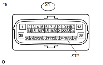
CHECK HARNESS AND CONNECTOR (STP TERMINAL) |
|
(a) Turn the ignition switch off. |
|
(b) Make sure that there is no looseness at the locking part and the connecting part of the connector.
(c) Disconnect the skid control ECU (brake actuator assembly) connector.
(d) Measure the voltage according to the value(s) in the table below.
Standard Voltage:
|
Tester Connection |
Switch Condition |
Specified Condition |
|---|---|---|
|
S1-35 (STP) - Body ground |
Stop light switch assembly on (Brake pedal depressed) |
8 to 14 V |
|
Stop light switch assembly off (Brake pedal released) |
Below 1.5 V |
|
*a |
Front view of wire harness connector (to Skid Control ECU [Brake Actuator Assembly]) |
| OK | |
REPLACE BRAKE ACTUATOR ASSEMBLY |
| NG | |
REPAIR OR REPLACE HARNESS OR CONNECTOR (STP CIRCUIT) |
 Open or Short in Master Cylinder Pressure Sensor (C1421,C1423,C1424,C142A,C1449)
DESCRIPTION
DTC No.
Detection Item
DTC Detection Condition
Trouble Area
C1421
Open or Short in Master Cylinder Pressure Sensor
...
 Open in Stop Light Switch Circuit (C1425)
DESCRIPTION
The skid control ECU (brake actuator assembly) detects the brake operating conditions
through a signal transmitted by the stop light switch.
The skid control ECU incorporates a circuit ...
Other materials:
Installation
INSTALLATION
PROCEDURE
1. INSTALL REAR BUMPER ASSEMBLY
(a) Using an engine lifter or equivalent, engage the 2 pins to install the rear
bumper assembly as shown in the illustration.
Text in Illustration
*a
Pin
-
-
NOTICE:
Using pl ...
Installation
INSTALLATION
PROCEDURE
1. INSTALL FRONT DRIVE SHAFT
(a) Coat the spline of the inboard joint shaft with gear oil.
(b) Align the shaft splines and install the front drive shaft with a brass bar
and hammer.
NOTICE:
Set the snap ring with the opening side facing downward.
Be caref ...
Evaporator Temperature Sensor Circuit (B1413)
DESCRIPTION
The cooler thermistor sensor (evaporator temperature sensor) is installed on
the evaporator in the air conditioner unit to detect the temperature of the cooled
air that has passed through the evaporator and is used to control the air conditioning.
It sends signals to the air condi ...
