Toyota Tacoma (2015-2018) Service Manual: LVDS Signal Malfunction (from Extension Module) (B1532,B156C)
DESCRIPTION
|
DTC Code |
DTC Detection Condition |
Trouble Area |
|---|---|---|
|
B1532 |
When one of the conditions below is met:
|
|
|
B156C |
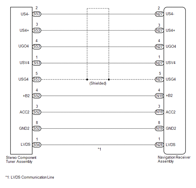
WIRING DIAGRAM
CAUTION / NOTICE / HINT
NOTICE:
After replacing the stereo component tuner assembly of vehicles subscribed to pay-type satellite radio broadcasts, XM radio ID registration is necessary. (w/ SDARS System)
PROCEDURE
|
1. |
CHECK DTC |
(a) Clear the DTCs (See page .gif) ).
).
(b) Check for DTCs (See page ).
OK:
No DTCs are output.
| OK | .gif) |
USE SIMULATION METHOD TO CHECK |
|
.gif)
|
2. |
CHECK HARNESS AND CONNECTOR (NAVIGATION RECEIVER ASSEMBLY - STEREO COMPONENT TUNER ASSEMBLY) |
(a) Disconnect the N19, N27 and N28 navigation receiver assembly connectors.
(b) Disconnect the S52, S53 and S54 stereo component tuner assembly connectors.
(c) Measure the resistance according to the value(s) in the table below.
Standard Resistance:
|
Tester Connection |
Condition |
Specified Condition |
|---|---|---|
|
N27-1 (USV4) - S53-1 (USV4) |
Always |
Below 1 Ω |
|
N27-2 (US4-) - S53-2 (US4-) |
Always |
Below 1 Ω |
|
N27-3 (US4+) - S53-3 (US4+) |
Always |
Below 1 Ω |
|
N27-4 (UGO4) - S53-4 (UGO4) |
Always |
Below 1 Ω |
|
N27-5 (USG4) - S53-5 (USG4) |
Always |
Below 1 Ω |
|
N19-4 (+B2) - S52-4 (+B) |
Always |
Below 1 Ω |
|
N19-3 (ACC2) - S52-3 (ACC2) |
Always |
Below 1 Ω |
|
N19-8 (GND2) - S52-8 (GND2) |
Always |
Below 1 Ω |
|
N28-1 (LVDS) - S54-1 (LVDS) |
Always |
Below 1 Ω |
|
N27-1 (USV4) - Body ground |
Always |
10 kΩ or higher |
|
N27-2 (US4-) - Body ground |
Always |
10 kΩ or higher |
|
N27-3 (US4+) - Body ground |
Always |
10 kΩ or higher |
|
N27-4 (UGO4) - Body ground |
Always |
10 kΩ or higher |
|
N27-5 (USG4) - Body ground |
Always |
10 kΩ or higher |
|
N19-4 (+B2) - Body ground |
Always |
10 kΩ or higher |
|
N19-3 (ACC2) - Body ground |
Always |
10 kΩ or higher |
|
N19-8 (GND2) - Body ground |
Always |
10 kΩ or higher |
|
N28-1 (LVDS) - Body ground |
Always |
10 kΩ or higher |
| NG | |
REPAIR OR REPLACE HARNESS OR CONNECTOR |
|
|
3. |
CHECK NO. 1 NAVIGATION WIRE |
(a) Replace the No. 1 navigation wire with a known good one (See page
).
(b) Clear the DTCs (See page ).
(c) Check for DTCs (See page ).
OK:
No DTCs are output.
| OK | |
END (NO. 1 NAVIGATION WIRE WAS DEFECTIVE) |
|
|
4. |
CHECK STEREO COMPONENT TUNER ASSEMBLY |
(a) Replace the stereo component tuner assembly with a known good one (See page
).
(b) Clear the DTCs (See page ).
(c) Check for DTCs (See page ).
OK:
No DTCs are output.
| OK | |
END (STEREO COMPONENT TUNER ASSEMBLY IS DEFECTIVE) |
| NG | |
REPLACE NAVIGATION RECEIVER ASSEMBLY |
 Lost Communication with Meter (B1324)
DESCRIPTION
This DTC is stored when a communication error occurs between the navigation receiver
assembly and combination meter assembly.
DTC No.
DTC Detection Condition
...
 HD Radio Tuner Malfunction (B1551,B15A0,B15AD,B15B0,B15B3,B15B4,B15B7)
DESCRIPTION
These DTCs are stored when a malfunction occurs in the navigation receiver assembly.
DTC No.
DTC Detection Condition
Trouble Area
B1551
...
Other materials:
Radio Broadcast cannot be Received or Poor Reception
PROCEDURE
1.
CHECK NAVIGATION RECEIVER ASSEMBLY
(a) Check the radio automatic station search function.
(1) Check the radio automatic station search function by activating it.
Result
Result
Proceed to
Automatic station search ...
Precaution
PRECAUTION
1. IGNITION SWITCH EXPRESSIONS
(a) The type of ignition switch used on this model differs depending on the specifications
of the vehicle. The expressions listed in the table below are used in this section.
Expression
Ignition Switch (Position)
Engine ...
Precaution
PRECAUTION
1. EXPRESSIONS OF IGNITION SWITCH
HINT:
The type of ignition switch used on this model differs according to the specifications
of the vehicle. The expressions listed in the table below are used in this section.
Expression
Ignition Switch
(Position)
...
