Toyota Tacoma (2015-2018) Service Manual: Lost Communication with Meter (B1324)
DESCRIPTION
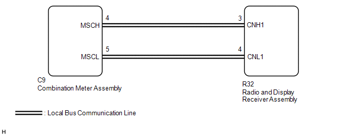
This DTC is stored when a communication error occurs between the radio and display receiver assembly and combination meter assembly.
|
DTC No. |
DTC Detection Condition |
Trouble Area |
|---|---|---|
|
B1324 |
After the radio and display receiver assembly receives a registration information signal, which is sent by the combination meter assembly when the ignition switch is turned to ACC, 1 or more times, the radio and display receiver assembly does not receive the signal for 30 seconds or more. |
|
WIRING DIAGRAM
PROCEDURE
|
1. |
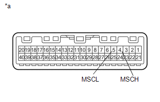
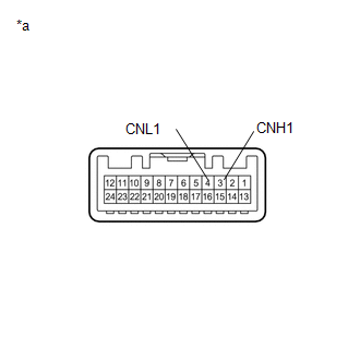
CHECK HARNESS AND CONNECTOR (RADIO AND DISPLAY RECEIVER ASSEMBLY - COMBINATION METER ASSEMBLY) |
(a) Disconnect the R32 radio and display receiver assembly connector.
(b) Disconnect the C9 combination meter assembly connector.
(c) Measure the resistance according to the value(s) in the table below.
Standard Resistance:
|
Tester Connection |
Condition |
Specified Condition |
|---|---|---|
|
R32-3 (CNH1) - C9-4 (MSCH) |
Always |
Below 1 Ω |
|
R32-4 (CNL1) - C9-5 (MSCL) |
Always |
Below 1 Ω |
|
R32-3 (CNH1) - Body ground |
Always |
10 kΩ or higher |
|
R32-4 (CNL1) - Body ground |
Always |
10 kΩ or higher |
|
R32-3 (CNH1) - R32-4 (CNL1) |
Always |
10 kΩ or higher |
(d) Measure the voltage according to the value(s) in the table below.
Standard Voltage:
|
Tester Connection |
Condition |
Specified Condition |
|---|---|---|
|
R32-3 (CNH1) - Body ground |
Always |
Below 1 V |
|
R32-4 (CNL1) - Body ground |
Always |
Below 1 V |
| NG | .gif) |
REPAIR OR REPLACE HARNESS OR CONNECTOR |
|
.gif)
|
2. |
INSPECT COMBINATION METER ASSEMBLY |
(a) Remove the combination meter assembly (See page
.gif) ).
).
|
(b) Measure the resistance according to the value(s) in the table below. Standard Resistance:
|
|
| NG | |
REPLACE COMBINATION METER ASSEMBLY |
|
|
3. |
INSPECT RADIO AND DISPLAY RECEIVER ASSEMBLY |
(a) Remove the radio and display receiver assembly (See page
).
|
(b) Measure the resistance according to the value(s) in the table below. Standard Resistance:
|
|
| NG | |
REPLACE RADIO AND DISPLAY RECEIVER ASSEMBLY |
|
|
4. |
REPLACE COMBINATION METER ASSEMBLY |
(a) Replace the combination meter assembly with a new or known good one (See
page ).
(b) Clear the DTCs (See page ).
(c) Recheck for DTCs and check that no DTCs are output.
OK:
No DTCs are output.
| NG | |
REPLACE RADIO AND DISPLAY RECEIVER ASSEMBLY |
|
|
5. |
CHECK METER / GAUGE SYSTEM |
(a) Turn the ignition switch to ON and wait 30 seconds.
(b) Operate the steering pad switch assembly and check that the audio tab is displayed on the multi-information display in the combination meter assembly and the audio system can be operated normally.
OK:
Audio system returns to normal.
| OK | |
END |
| NG | |
REPLACE RADIO AND DISPLAY RECEIVER ASSEMBLY |
 Diagnostic Trouble Code Chart
DIAGNOSTIC TROUBLE CODE CHART
Audio and Visual System
DTC Code
Detection Item
See page
B1324
Lost Communication with Meter
...
 LVDS Signal Malfunction (from Extension Module) (B1532)
DESCRIPTION
The stereo component tuner assembly and the radio and display receiver assembly
are connected by an LVDS communication line.
This DTC is stored when an LVDS communication error occurs ...
Other materials:
Installation
INSTALLATION
PROCEDURE
1. INSTALL HYDRAULIC BRAKE BOOSTER
(a) Install a new brake booster gasket onto the hydraulic brake booster.
(b) Install the hydraulic brake booster with the 4 nuts.
Torque:
14 N·m {145 kgf·cm, 10 ft·lbf}
(c) Using a union nut wrench, connect the 4 brake l ...
Replacement
REPLACEMENT
CAUTION / NOTICE / HINT
CAUTION:
Prolonged and repeated contact with engine oil will result in the removal
of natural oils from the skin, leading to dryness, irritation and dermatitis.
In addition, used engine oil contains potentially harmful contaminants which
may ...
Accumulator Low Pressure (C1256)
DESCRIPTION
The accumulator pressure sensor is connected to the skid control ECU in the master
cylinder solenoid.
DTC No.
DTC Detecting Condition
Trouble Areas
C1256
Fluid pressure inside the accumulator drops below the specification ...
