Toyota Tacoma (2015-2018) Service Manual: Installation
INSTALLATION
PROCEDURE
1. INSTALL HYDRAULIC BRAKE BOOSTER
(a) Install a new brake booster gasket onto the hydraulic brake booster.
(b) Install the hydraulic brake booster with the 4 nuts.
Torque:
14 N·m {145 kgf·cm, 10 ft·lbf}
|
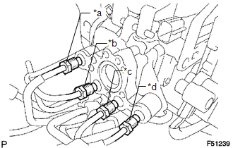
(c) Using a union nut wrench, connect the 4 brake lines to the correct positions of the hydraulic brake booster, as shown in the illustration. Text in Illustration
Torque: without union nut wrench : 15 N·m {155 kgf·cm, 11 ft·lbf} with union nut wrench : 14 N·m {145 kgf·cm, 10 ft·lbf} HINT:
|
|
(d) Connect the 3 connectors.
2. INSTALL MASTER CYLINDER PUSH ROD CLEVIS
.gif)
3. INSTALL LOWER NO. 1 INSTRUMENT PANEL AIRBAG ASSEMBLY
(See page )
4. INSPECT BRAKE PEDAL HEIGHT
5. INSPECT PEDAL FREE PLAY
6. INSPECT PEDAL RESERVE DISTANCE
7. FILL RESERVOIR WITH BRAKE FLUID
8. BLEED BRAKE BOOSTER WITH ACCUMULATOR PUMP ASSEMBLY
9. BLEED BRAKE LINE
10. BLEED MASTER CYLINDER SOLENOID
11. INSPECT FLUID LEVEL IN RESERVOIR
12. INSPECT FOR BRAKE FLUID LEAK
13. INSPECT BRAKE MASTER CYLINDER OPERATION
 Disposal
DISPOSAL
PROCEDURE
1. DISPOSE OF BRAKE BOOSTER ACCUMULATOR ASSEMBLY
(a) Place the brake booster accumulator in a vise and cover it with a cloth.
(b) Slowly cut a hole on the brake booster accumu ...
 Rear Brake
...
Other materials:
Installation
INSTALLATION
PROCEDURE
1. SET NO. 1 CYLINDER TO TDC/COMPRESSION
2. INSTALL CAMSHAFT TIMING GEAR BOLT
NOTICE:
There are different types of camshaft timing gear bolts. Make sure to check the
identification mark to determine the tightening torque.
*a
Identification Ma ...
Inspection
INSPECTION
PROCEDURE
1. INSPECT BRAKE BOOSTER PUMP ASSEMBLY
(a) Connect the positive (+) lead from the battery to the red cable of the pump,
and the negative (-) lead to the black cable.
(b) Check the brake booster pump operation.
OK:
Operation sound is heard. ...
Dtc Check / Clear
DTC CHECK / CLEAR
1. CHECK DTC
(a) Connect the Techstream to the DLC3.
(b) Turn the ignition switch to ON.
(c) Turn the Techstream on.
(d) Enter the following menus: Body Electrical / Sliding Roof / Trouble Codes.
(e) Check the details of the DTC(s) (See page
).
2. CLEAR DTC
(a) Connect th ...
