Toyota Tacoma (2015-2018) Service Manual: Accumulator Low Pressure (C1256)
DESCRIPTION
The accumulator pressure sensor is connected to the skid control ECU in the master cylinder solenoid.
.png)
|
DTC No. |
DTC Detecting Condition |
Trouble Areas |
|---|---|---|
|
C1256 |
Fluid pressure inside the accumulator drops below the specification value. |
|
PROCEDURE
|
1. |
RECONFIRM DTC |
(a) Clear the DTCs (See page .gif) ).
).
(b) Turn the ignition switch to OFF.
(c) Depress the brake pedal 20 times or more.
(d) Turn the ignition switch to the ON position.
(e) Wait for 99 seconds.
(f) Check if the same DTCs are recorded.
|
Result |
Proceed to |
|---|---|
|
DTC output |
A |
|
DTC not output |
B |
| B | .gif) |
END |
|
.gif)
|
2. |
INSPECT HYDRAULIC BRAKE BOOSTER ASSEMBLY FUNCTION |
(a) Inspect brake booster pump power supply system function.
(1) Turn the ignition switch off.
(2) Depress the brake pedal 20 times or more to release the pressure in the accumulator.
HINT:
When the pressure is released, the brake pedal stroke becomes longer.
(3) Check that the brake fluid level is at the MAX level.
(4) Chock the 4 wheels and release the parking brake.
(5) Turn the ignition switch to ON and measure the brake booster pump operating time (the time from when the brake booster pump starts operating until it stops).
OK:
20 to 80 seconds
(6) Start the engine after the brake boost pump stops.
(7) Check that the ABS warning light and slip indicator light are not illuminated.
(8) Turn off the engine, and then turn the ignition switch to ON.
(9) Check that the brake boost pump operates and then stops when the brake pedal is depressed 4 or 5 times.
(10) Depress the brake pedal 4 or 5 times and measure the brake booster pump operating time (the time from when the brake booster pump starts operating until it stops).
OK:
2 to 11 seconds
(11) Check that the brake warning light illuminates and the buzzer sounds when the brake pedal is fully depressed continuously 15 to 20 times.
NOTICE:
Wait 120 seconds or more after turning the ignition switch to ON before performing this inspection.
(b) Check brake booster operation.
(1) Turn the ignition switch off.
(2) Depress the brake pedal 20 times or more to release the pressure in the accumulator.
HINT:
When the pressure is released, the brake pedal stroke becomes longer.
(3) Depress the brake pedal, start the engine, and check the change in the brake pedal height.
OK:
The brake pedal moves slightly inward.
(c) Inspect brake master cylinder fluid pressure change (See page
).
| NG | |
GO TO STEP 5 |
|
|
3. |
READ VALUE USING DATA LIST (ACCUMULATOR SENSOR) |
(a) Connect Techstream to the DLC3.
(b) Turn the ignition switch to the ON position.
(c) Turn Techstream ON.
(d) Select the "Data List" mode on the Techstream.
ABS/VSC/TRAC|
Tester Display |
Measurement Item / Range |
Normal Condition |
Diagnostic Note |
|---|---|---|---|
|
Accumulator Sensor |
Accumulator pressure sensor reading / min.: 0 V, max.: 5 V |
3.58 to 5 V |
If value constant regardless of pump operation, accumulator pressure sensor malfunction suspected. |
(e) Check that the accumulator's output value is in the Normal Condition range.
OK:
Accumulator pressure sensor value is in the Normal Condition.
| NG | |
REPLACE MASTER CYLINDER SOLENOID |
|
|
4. |
RECONFIRM DTC |
(a) Clear the DTCs (See page
).
(b) Check if the same DTCs are recorded.
|
Result |
Proceed to |
|---|---|
|
DTC output |
A |
|
DTC not output |
B |
| A | |
REPLACE MASTER CYLINDER SOLENOID |
| B | |
END |
|
5. |
INSPECT BRAKE BOOSTER PUMP ASSEMBLY |
(a) Remove the hydraulic brake booster assembly (See page
).
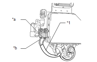
(b) Using a screwdriver, remove the 2 screws and pull out the wire harness from the master cylinder solenoid.
|
(c) Measure the resistance according to the value(s) in the table below. Standard Resistance:
|
|
(d) Install the pump motor wire harness to the master cylinder solenoid with the 2 screws.
Torque:
2.9 N·m {30 kgf·cm, 26 in·lbf}
| OK | |
REPLACE HYDRAULIC BRAKE BOOSTER ASSEMBLY |
| NG | |
REPLACE BRAKE BOOSTER WITH ACCUMULATOR PUMP ASSEMBLY |
 Pressure Sensor or Switch (C1254)
DESCRIPTION
The accumulator pressure sensor is connected to the skid control ECU in the master
cylinder solenoid.
DTC No.
DTC Detecting Condition
Trouble Areas
...
 Power Supply Drive Circuit (C1257)
DESCRIPTION
The motor relay (semiconductor relay) is built into the hydraulic brake booster
and drives the pump motor based on a signal from the skid control ECU (master cylinder
solenoid).
...
Other materials:
Problem Symptoms Table
PROBLEM SYMPTOMS TABLE
HINT:
Use the table below to help determine the cause of problem symptoms. If multiple
suspected areas are listed, the potential causes of the symptoms are listed in order
of probability in the "Suspected Area" column of the table. Check each symptom by
check ...
Seatback table
Front passenger’s seatback can be used as a temporary table only when the
vehicle is stopped.
Fold down the front passenger’s seat to use the seatback table.
CAUTION
■Caution while driving
Observe the following precautions to avoid death or serious injury.
●Do not set up the ...
Adjustment
ADJUSTMENT
CAUTION / NOTICE / HINT
CAUTION:
Radiofrequency radiation exposure information:
This equipment complies with FCC radiation exposure limits set forth
for an uncontrolled environment.
This equipment should be kept with minimum distance of 20 cm (7.87 in.)
between the ...
