Toyota Tacoma (2015-2018) Service Manual: Adjustment
ADJUSTMENT
PROCEDURE
1. PREPARE VEHICLE FOR FOG LIGHT AIMING ADJUSTMENT
(a) Prepare the vehicle:
HINT:
- Ensure that there is no damage or deformation to the body around the fog lights.
- Fill the fuel tank.
- Make sure that the oil is filled to the specified level.
- Make sure that the coolant is filled to the specified level.
- Inflate the tires to the appropriate pressure.
- Place the spare tire, tools, and jack in their original positions.
- Unload the trunk.
- Sit a person of average weight (68 kg, 150 lb) in the driver side seat.
2. PREPARE FOR FOG LIGHT AIMING
|
(a) Prepare the vehicle according to the following conditions: HINT:
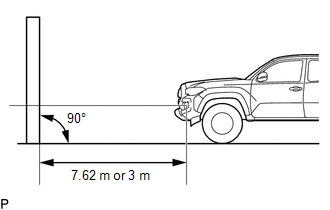
NOTICE: A distance of 7.62 m (25 ft) between the vehicle (center of the fog light bulb) and the wall is necessary for proper aim adjustment. If unavailable to secure a distance of 7.62 m (25 ft), secure a distance of exactly 3 m (9.84 ft) to check and adjust the fog light aim. (Since the target zone will change with the distance, follow the instructions shown in the illustration.) |
|
(b) Prepare a piece of thick white paper (approximately 2 m (6.56 ft) (height) x 4 m (13.1 ft) (width)) to use as a screen.
(c) Draw a vertical line down the center of screen (V line).
(d) Set the screen as shown in the illustration.
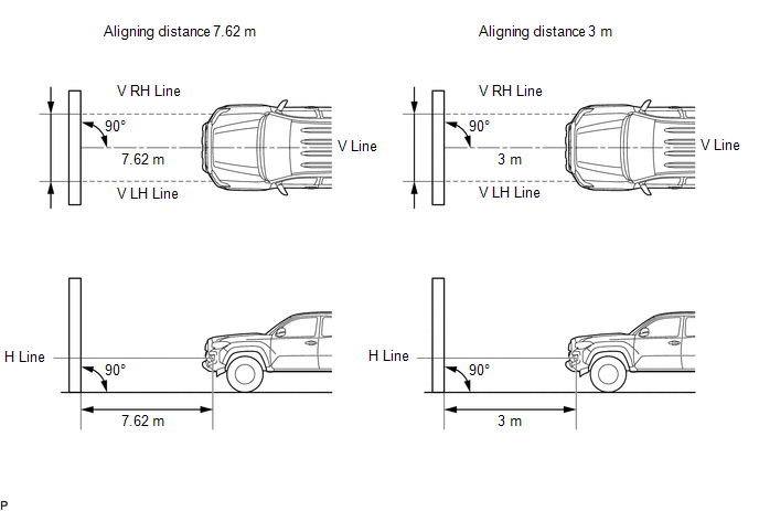
HINT:
- Stand the screen perpendicular to the ground.
- Align the V line on the screen with the center of the vehicle.
|
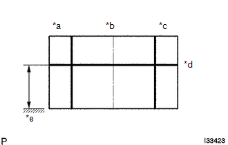
(e) Draw base lines (H line, V LH, V RH lines) on the screen as shown in the illustration. Text in Illustration
HINT: Mark the fog light bulb center marks on the screen. If the center mark cannot be observed on the fog light, use the center of the fog light bulb or the manufacturer's name marked on the fog light as the center mark. (1) H Line (Fog light height): Draw a horizontal line across the screen so that it passes through the center marks. The H line should be at the same height as the fog light bulb center marks of the low-beam fog lights. (2) V LH Line, V RH Line (Center mark position of left-hand (LH) and right-hand (RH) fog lights): Draw two vertical lines so that they intersect the H line at each center mark. |
|
3. INSPECT FOG LIGHT AIMING
(a) Cover the fog light or disconnect the connector of the fog light on the opposite side to prevent light from the fog light not being inspected from affecting fog light aiming inspection.
(b) Start the engine.
NOTICE:
Engine speed must be 1500 or more.
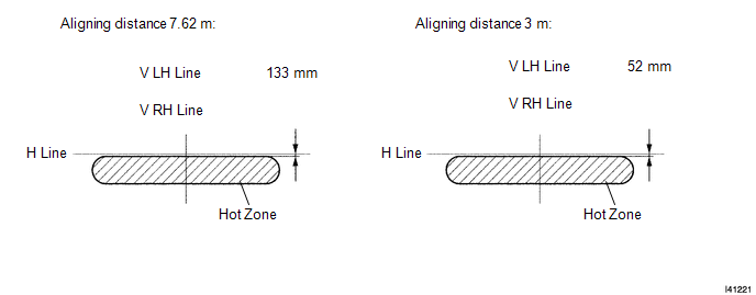
(c) Turn on the fog light and make sure that the cutoff line falls within the specified area, as shown in the illustration.
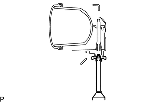
4. ADJUST FOG LIGHT AIMING
|
(a) Adjust the fog light aim into the specified range by turning the aiming screw with a screwdriver. NOTICE: The final turn of the aiming screw should be made in the clockwise direction. If the screw is tightened excessively, loosen it and then retighten it, so that the final turn of the screw is in the clockwise direction. |
|
 Removal
REMOVAL
CAUTION / NOTICE / HINT
HINT:
Use the same procedure for both the LH and RH sides.
The procedure described below is for the LH side.
PROCEDURE
1. REMOVE NO. 1 FRONT WHEE ...
 Reassembly
REASSEMBLY
CAUTION / NOTICE / HINT
HINT:
Use the same procedure for both the LH and RH sides.
The procedure described below is for the LH side.
PROCEDURE
1. INSTALL FOG LIGHT BU ...
Other materials:
How To Proceed With Troubleshooting
CAUTION / NOTICE / HINT
HINT:
Use this procedure to troubleshoot the theft deterrent system.
*: Use the Techstream.
PROCEDURE
1.
VEHICLE BROUGHT TO WORKSHOP
NEXT
2.
...
Inspection
INSPECTION
PROCEDURE
1. INSPECT BRAKE BOOSTER PUMP ASSEMBLY
(a) Connect the positive (+) lead from the battery to the red cable of the pump,
and the negative (-) lead to the black cable.
(b) Check the brake booster pump operation.
OK:
Operation sound is heard. ...
Driver Side Door Entry Unlock Function does not Operate
DESCRIPTION
If the entry unlock function does not operate for the driver door only, but the
entry lock function operates, the request code is being transmitted properly from
the driver door. In this case, there may be a problem related to the touch sensor
(connection between the certification ...
