Toyota Tacoma (2015-2018) Service Manual: Installation
INSTALLATION
CAUTION / NOTICE / HINT
HINT:
Perform "Inspection After Repairs" after replacing the fuel delivery pipe assembly
LH (fuel pressure sensor) (See page .gif) ).
).
PROCEDURE
1. INSTALL FUEL PIPE PLUG SUB-ASSEMBLY
(a) Install a new O-ring, new No. 1 fuel injector back-up ring, new No. 2 fuel injector back-up ring and new No. 3 fuel injector back-up ring to the fuel pipe plug sub-assembly as shown in the illustration.
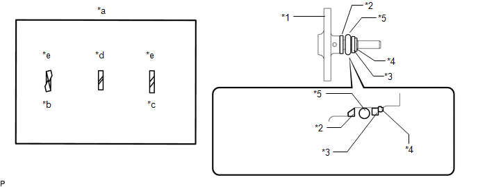 Text in Illustration
|
*1 |
Fuel Pipe Plug Sub-assembly |
*2 |
No. 1 Fuel Injector Back-up Ring |
|
*3 |
No. 3 Fuel Injector Back-up Ring |
*4 |
No. 3 Fuel Injector Back-up Ring |
|
*5 |
O-ring |
- |
- |
|
*a |
Opening |
*b |
Overlapping |
|
*c |
Stretched |
*d |
Correct |
|
*e |
Incorrect |
- |
- |
NOTICE:
- Check that there is no foreign matter or damage on the O-ring groove of the fuel pipe plug sub-assembly.
- Check that the No. 1 fuel injector back-up ring and No. 3 fuel injector back-up ring are installed in the correct orientation.
- Make sure that the No. 1 fuel injector back-up ring, No. 2 fuel injector back-up ring, No. 3 fuel injector back-up ring and O-ring are installed in the correct order.
- Check that the alignment of the No. 1 fuel injector back-up ring is not overlapped or stretched as shown in the illustration.
- After installing the O-ring, check that it is not contaminated with foreign matter and is not damaged.
(b) Secure the fuel delivery pipe assembly LH in a vise between aluminum plates.
NOTICE:
Do not overtighten the vise.
|
(c) Install a new gasket to the fuel pipe plug sub-assembly as shown in the illustration. |
|
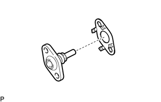
(d) Using a 5 mm hexagon wrench, install the fuel pipe plug sub-assembly to the fuel delivery pipe assembly LH with the 2 bolts.
Torque:
10 N·m {102 kgf·cm, 7 ft·lbf}
(e) Install a new dust cap sub-assembly to the fuel pipe plug sub-assembly.
2. INSTALL FUEL DELIVERY PIPE ASSEMBLY LH (FUEL PRESSURE SENSOR)
(See page )
NOTICE:
- Do not remove the fuel pressure sensor from the fuel delivery pipe sub-assembly LH.
- If a fuel pressure sensor is removed, replace the fuel delivery pipe sub-assembly LH (fuel pressure sensor) with a new one.
HINT:
Perform "Inspection After Repairs" after replacing the fuel delivery pipe assembly
LH (fuel pressure sensor) (See page ).
 Inspection
INSPECTION
PROCEDURE
1. INSPECT FUEL DELIVERY PIPE SUB-ASSEMBLY LH (FUEL PRESSURE SENSOR)
NOTICE:
Do not remove the fuel pressure sensor from the fuel delivery pipe sub-assembly
LH.
...
 Fuel Pump
...
Other materials:
Diagnosis System
DIAGNOSIS SYSTEM
1. DESCRIPTION
The 4 wheel drive control ECU records DTCs when the ECU detects a malfunction
in the ECU itself or in system circuits.
The DTCs can be read through the DLC3 of the vehicle. When the system seems to
be malfunctioning, use the Techstream to check for malfunctions ...
Rear Differential Lock Position SW Stuck OFF (P17BB)
DESCRIPTION
This DTC is output when an OFF malfunction of the differential lock indicator
switch is detected.
DTC No.
Detection Item
DTC Detection Condition
Trouble Area
P17BB
Rear Differential Lock Position SW Stuck OFF
...
Terminals Of Ecu
TERMINALS OF ECU
1. CHECK CERTIFICATION ECU (SMART KEY ECU ASSEMBLY)
(a) Disconnect the C27 and C29 certification ECU (smart key ECU assembly) connectors.
(b) Measure the voltage and resistance according to the value(s) in the table
below.
HINT:
Measure the values on the wire harness side w ...
