Toyota Tacoma (2015-2018) Service Manual: Installation
INSTALLATION
PROCEDURE
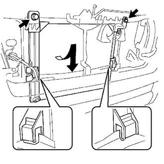
1. INSTALL COOLER CONDENSER ASSEMBLY
(a) Engage the 2 claws to install the 2 condenser upper brackets.
(b) Engage the 2 claws to install the 2 condenser lower brackets.
|
(c) Lift the cooler condenser assembly up from the rear side of the vehicle, and install the condenser lower brackets onto the upper part of the radiator lower supports with the 2 bolts. Torque: 9.0 N·m {92 kgf·cm, 80 in·lbf} |
|
2. INSTALL AIR CONDITIONING TUBE ASSEMBLY
(a) Remove the vinyl tape from the air conditioning tube assembly and connecting part of the cooler condenser assembly.
(b) Apply sufficient compressor oil to a new O-ring and fitting surface of the cooler condenser assembly.
Compressor oil:
PSD1 or equivalent
(c) Install the O-ring to the air conditioning tube assembly.
(d) Install the air conditioning tube assembly to the cooler condenser assembly with the bolt.
Torque:
9.8 N·m {100 kgf·cm, 87 in·lbf}
3. INSTALL DISCHARGE HOSE SUB-ASSEMBLY
(a) Remove the vinyl tape from the discharge hose sub-assembly and connecting part of the cooler condenser assembly.
(b) Apply sufficient compressor oil to a new O-ring and fitting surface of the cooler condenser assembly.
Compressor oil:
PSD1 or equivalent
(c) Install the O-ring to the discharge hose sub-assembly.
(d) Install the discharge hose sub-assembly to the cooler condenser assembly with the bolt.
Torque:
9.8 N·m {100 kgf·cm, 87 in·lbf}
4. INSTALL RADIATOR ASSEMBLY (for 2TR-FE)
Click here .gif)
5. INSTALL RADIATOR ASSEMBLY (for 2GR-FKS)
Click here
6. CONNECT CABLE TO NEGATIVE BATTERY TERMINAL
Torque:
5.4 N·m {55 kgf·cm, 48 in·lbf}
NOTICE:
When disconnecting the cable, some systems need to be initialized after the cable is reconnected.
Click here
7. CHARGE AIR CONDITIONING SYSTEM WITH REFRIGERANT
Click here
8. WARM UP ENGINE
Click here
9. INSPECT FOR REFRIGERANT LEAK
Click here
 Removal
REMOVAL
PROCEDURE
1. PRECAUTION
NOTICE:
After turning the ignition switch off, waiting time may be required before disconnecting
the cable from the negative (-) battery terminal. Therefore, make ...
 Front Blower Motor
Inspection
INSPECTION
PROCEDURE
1. INSPECT BLOWER MOTOR
(a) Inspect the blower motor.
(1) Connect the positive (+) lead from to terminal 1 and negative (-)
lead to terminal 2, ...
Other materials:
Electronic Circuit Inspection Procedure
ELECTRONIC CIRCUIT INSPECTION PROCEDURE
1. BASIC INSPECTION
(a) WHEN MEASURING RESISTANCE OF ELECTRONIC PARTS
(1) Unless otherwise stated, all resistance measurements should be made at an
ambient temperature of 20°C (68°F). Resistance measurements may be inaccurate if
measured at high tempe ...
Dtc Check / Clear
DTC CHECK / CLEAR
1. CHECK DTC (CHECK USING TECHSTREAM)
(a) Connect the Techstream to the DLC3.
(b) Turn the ignition switch to ON.
(c) Turn the Techstream on.
(d) Enter the following menus: Body Electrical / Navigation System / Trouble
Codes.
(e) Check for DTCs, and then write them down.
( ...
Reverse Signal Circuit
DESCRIPTION
The radio and display receiver assembly*1 or navigation receiver assembly*2 receives
a reverse signal from the park/neutral position switch*3 or the back-up light switch
assembly*4.
*1: w/o Navigation System
*2: w/ Navigation System
*3: for Automatic Transmission
...
