Toyota Tacoma (2015-2018) Service Manual: Installation
INSTALLATION
PROCEDURE
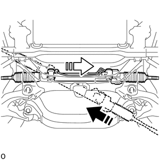
1. INSTALL POWER STEERING LINK
(a) Insert the power steering link into the vehicle in the order shown in the illustration.
.png) |
Install in this Direction (1) |
.png) |
Install in this Direction (2) |
|
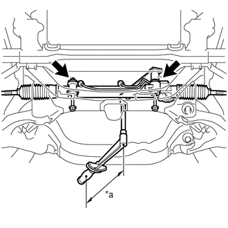
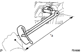
(b) Using SST, install the power steering link with the 2 bolts and 2 nuts. SST: 09961-01270 Torque: Specified tightening torque : 95 N·m {969 kgf·cm, 70 ft·lbf} NOTICE: While holding the nut in place, tighten the bolt. HINT:
|
|
2. CONNECT PRESSURE FEED TUBE ASSEMBLY
(a) Connect the return hose and slide the clip to secure it.
|
(b) Using a 17 mm union nut wrench, tighten the flare nut and connect the pressure feed tube. Torque: Specified tightening torque : 24 N·m {245 kgf·cm, 18 ft·lbf} NOTICE: Do not damage the pressure feed tube. HINT:
|
|
(c) Install the tube support brackets with the 2 bolts.
Torque:
28 N·m {286 kgf·cm, 21 ft·lbf}
3. INSTALL TIE ROD END SUB-ASSEMBLY LH
Click here .gif)
4. INSTALL TIE ROD END SUB-ASSEMBLY RH
HINT:
Use the same procedure described for the LH side.
5. PLACE FRONT WHEELS FACING STRAIGHT AHEAD
6. INSTALL NO. 2 STEERING INTERMEDIATE SHAFT
|
(a) Align the matchmarks on the No. 2 steering intermediate shaft and power steering link. |
|
.png)
(b) Install the No. 2 steering intermediate shaft to the power steering link with bolt C.
Torque:
35 N·m {357 kgf·cm, 26 ft·lbf}
|
(c) Align the matchmarks on the steering intermediate shaft and steering sliding yoke. |
|
.png)
(d) Install the steering sliding yoke to the steering intermediate shaft and slide it upward.
(e) Align the matchmarks on the steering sliding yoke and No. 2 steering intermediate shaft.
(f) Install the steering sliding yoke to the No. 2 steering intermediate shaft with bolts A and B.
Torque:
35 N·m {357 kgf·cm, 26 ft·lbf}
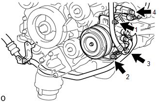
7. INSTALL COOLER COMPRESSOR ASSEMBLY
|
(a) Install the 2 bolts and 2 nuts in the order shown in the illustration. Torque: 21 N·m {214 kgf·cm, 16 ft·lbf} |
|
|
(b) Install the suction hose sub-assembly with the bolt. Torque: 7.5 N·m {76 kgf·cm, 66 in·lbf} |
|
.png)
(c) Install the fan and generator V belt.
Click here
8. INSTALL AUTOMATIC TRANSMISSION OIL COOLER TUBE (for Automatic Transmission)
|
(a) Install the automatic transmission oil cooler tube and clamp with the bolt. Torque: 5.5 N·m {56 kgf·cm, 49 in·lbf} |
|
.png)
9. INSTALL FRONT DIFFERENTIAL CARRIER ASSEMBLY (for 4WD)
Click here
10. INSTALL NO. 1 ENGINE UNDER COVER SUB-ASSEMBLY
Torque:
30 N·m {306 kgf·cm, 22 ft·lbf}
11. INSTALL NO. 2 ENGINE UNDER COVER SUB-ASSEMBLY (w/ Off Road Package)
Torque:
30 N·m {306 kgf·cm, 22 ft·lbf}
12. INSTALL FRONT UPPER FENDER APRON SEAL
Click here
13. INSTALL FRONT WHEELS
Torque:
113 N·m {1152 kgf·cm, 83 ft·lbf}
14. INSPECT STEERING WHEEL CENTER POINT
15. ADD POWER STEERING FLUID
16. BLEED POWER STEERING FLUID
Click here
17. INSPECT FOR POWER STEERING FLUID LEAK
18. INSPECT AND ADJUST FRONT WHEEL ALIGNMENT
Click here
 Inspection
INSPECTION
PROCEDURE
1. INSPECT TIE ROD END SUB-ASSEMBLY
(a) Flip the ball joint stud back and forth 5 times as shown in the illustration
before installing the nut.
(b) Using a torque wrench, ...

Other materials:
Rear Occupant Classification Sensor LH Collision Detection (B1787)
DESCRIPTION
DTC B1787 is set when the occupant detection ECU receives a collision detection
signal, which is sent by the occupant classification sensor rear LH when an accident
occurs.
DTC B1787 is also set when the front seat with adjuster frame assembly RH is
subjected to a strong impact, ...
Installation
INSTALLATION
CAUTION / NOTICE / HINT
CAUTION:
Some of these service operations affect the SRS airbag system. Read the precautionary
notices concerning the SRS airbag system before servicing.
Click here
PROCEDURE
1. INSTALL FRONT SEAT INNER BELT ASSEMBLY
(a) for Driver Side:
(1) Install t ...
Maintenance requirements
To ensure safe and economical driving, day-to-day care and regular maintenance
is essential. It is the owner’s responsibility to perform regular checks. Toyota
recommends the following maintenance.
■ General maintenance
Should be performed on a daily basis. This can be done by yourself ...
