Toyota Tacoma (2015-2018) Service Manual: Installation
INSTALLATION
PROCEDURE
1. INSTALL TRANSFER ASSEMBLY
Click here .gif)
2. INSTALL WIRING HARNESS CLAMP BRACKET
(a) Install the 4 wiring harness clamp brackets with the 4 bolts.
Torque:
8.0 N·m {82 kgf·cm, 71 in·lbf}
3. INSTALL TRANSMISSION BREATHER SUB-ASSEMBLY
(a) Install the 2 brackets to the manual transmission assembly with the 2 bolts.
Torque:
19 N·m {194 kgf·cm, 14 ft·lbf}
(b) Install the transmission breather sub-assembly to the control shift lever retainer assembly.
(c) Attach the 3 breather hose clamps.
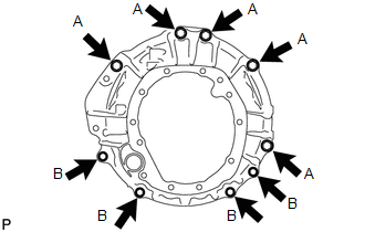
4. INSTALL MANUAL TRANSMISSION ASSEMBLY
|
(a) Install the manual transmission assembly with the 9 bolts. Torque: Bolt A : 72 N·m {730 kgf·cm, 53 ft·lbf} Bolt B : 37 N·m {380 kgf·cm, 28 ft·lbf} |
|
5. CONNECT WIRE HARNESS
(a) Attach the 10 clamps to install the wire harness.
(b) Connect the 3 connectors.
6. INSTALL REAR NO. 1 ENGINE MOUNTING INSULATOR
(a) Install the rear engine mounting insulator to the manual transmission assembly with the 4 bolts.
Torque:
58 N·m {591 kgf·cm, 43 ft·lbf}
7. INSTALL NO. 3 FRAME CROSSMEMBER SUB-ASSEMBLY
(a) Install the No. 3 frame crossmember sub-assembly with the 4 nuts and 4 bolts.
Torque:
40 N·m {408 kgf·cm, 30 ft·lbf}
(b) Install the 4 bolts to the No. 3 frame crossmember sub-assembly.
Torque:
21 N·m {214 kgf·cm, 15 ft·lbf}
8. INSTALL FRONT SUSPENSION MEMBER BRACKET LH AND RH
(a) Install the front suspension member bracket LH and front suspension member bracket RH to the No. 3 frame crossmember sub-assembly and vehicle body with the 8 bolts.
Torque:
33 N·m {337 kgf·cm, 24 ft·lbf}
9. INSTALL FRONT DIFFERENTIAL CARRIER ASSEMBLY
Click here
10. INSTALL PROPELLER SHAFT WITH CENTER BEARING ASSEMBLY
Click here
11. INSTALL STARTER ASSEMBLY
Click here
12. INSTALL NO. 2 MANIFOLD STAY
Click here
13. INSTALL MANIFOLD STAY
Click here
14. INSTALL FRONT EXHAUST PIPE ASSEMBLY
Click here
15. ADD MANUAL TRANSMISSION OIL
Click here
16. INSTALL NO. 1 FLOOR SHIFT BUSH
(a) Install the No. 1 floor shift bush to the floor shift shift lever assembly.
17. INSTALL FLOOR SHIFT SHIFT LEVER ASSEMBLY
(a) Apply MP grease to the tip of the floor shift shift lever assembly.
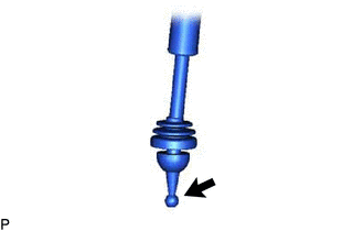 Text in Illustration
.png) |
MP grease |
|
(b) Cover the shift lever cap with a cloth. Text in Illustration
|
|
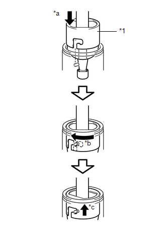
(c) While pressing down on the shift lever cap, turn it clockwise to install the shift lever assembly.
(d) Attach the shift lever cap boot to the manual transmission.
18. INSTALL SHIFT LEVER BOOT ASSEMBLY
(a) Install the shift lever boot assembly with the 2 screws and 2 clips.
19. INSTALL FRONT CONSOLE BOX
Click here
20. CONNECT CABLE TO NEGATIVE BATTERY TERMINAL
Torque:
5.4 N·m {55 kgf·cm, 48 in·lbf}
NOTICE:
When disconnecting the cable, some systems need to be initialized after the cable is reconnected.
Click here
 Components
COMPONENTS
ILLUSTRATION
ILLUSTRATION
...
 Removal
REMOVAL
PROCEDURE
1. PRECAUTION
NOTICE:
After turning the ignition switch off, waiting time may be required before disconnecting
the cable from the negative (-) battery terminal. Therefore, make ...
Other materials:
Terminals Of Ecu
TERMINALS OF ECU
1. CHECK 4 WHEEL DRIVE CONTROL ECU
Text in Illustration
*a
Component with harness connected
(4 Wheel Drive Control ECU)
-
-
(a) Measure the resistance and voltage according to the value(s) in the table
below.
...
Diagnostic Trouble Code Chart
DIAGNOSTIC TROUBLE CODE CHART
Central Gateway ECU (Network Gateway ECU)
DTC Code
Detection Item
See page
B1003
ECU Malfunction
...
Precaution
PRECAUTION
1. PRECAUTIONS WHEN CHECKING FOR DTCS
(a) When the cable is disconnected from the negative (-) battery terminal, the
DTCs stored in the steering lock ECU (steering lock actuator or UPR bracket assembly)
are cleared. Be sure to record any output DTCs immediately.
(b) Normally, with ...
