Toyota Tacoma (2015-2018) Service Manual: Reassembly
REASSEMBLY
PROCEDURE
1. INSPECT CENTER NO. 2 SUPPORT BEARING ASSEMBLY
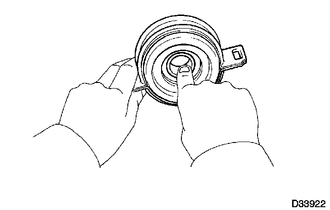
(a) When turning the center No. 2 support bearing assembly with your hand, check that it turns smoothly without catching and that there are no cracks or damage.
If there are any defects, replace it.
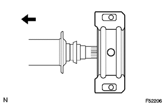
2. INSTALL CENTER NO. 2 SUPPORT BEARING ASSEMBLY
(a) Install the center No. 2 support bearing assembly to the propeller shaft with center bearing assembly.
 Text in Illustration
.png) |
Front |
(b) Coat the splines of the propeller shaft with center bearing assembly with MP grease.
(c) Install the 2 washers.
|
(d) Align the matchmarks on the universal joint yoke and propeller shaft with center bearing assembly. Text in Illustration
HINT: If replacing either the universal joint yoke or propeller shaft with center bearing assembly, assemble them so that the front side yoke of the propeller shaft with center bearing assembly and the universal joint yoke are facing in the same direction. |
|
(e) Install the plate washer.
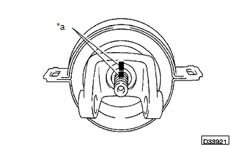
(f) Clamp the universal joint yoke in a vise, and press the bearing into position by tightening a new nut.
Torque:
200 N·m {2038 kgf·cm, 148 ft·lbf}
(g) Using a chisel and hammer, stake the lock nut.
3. INSTALL PROPELLER SHAFT UNIVERSAL JOINT SPIDER BEARING
.png)
(a) Apply MP grease to a new spider and bearings.
(b) Fit the spider into the flange yoke.
|
(c) Measure dimension A between the snap ring grooves. |
|
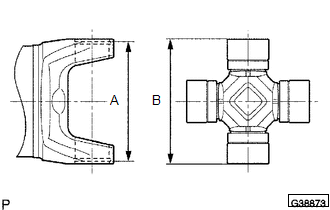
(d) Insert the spider bearing into the spider journal portion, and then measure dimension B of the universal joint.
NOTICE:
When measuring dimension B, fix the spider and spider bearings in a vise and hold them firmly together.
|
(e) Select snap rings to make dimensions A and B the same. Snap Ring Type:
NOTICE:
|
|
.png)
|
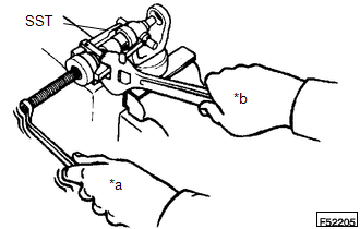
(f) Insert the spider into the yoke, and then using SST, press the spider bearing into the snap ring groove. Text in Illustration
SST: 09332-25010 |
|
(g) Press in the spider bearing on the opposite side in the same way.
NOTICE:
When pressing in the spider bearing, be careful not to damage its lip.
|
(h) Using needle-nose pliers, install 4 new snap rings into the grooves of the yoke. |
|
.png)
4. INSPECT PROPELLER SHAFT UNIVERSAL JOINT SPIDER BEARING
(a) Check the spider bearings for wear and damage.
(b) Check each spider bearing's axial play by turning the yoke while holding the shaft tightly.
Maximum bearing axial play:
0 to 0.05 mm (0 to 0.00197 in.)
 Installation
INSTALLATION
PROCEDURE
1. INSTALL PROPELLER SHAFT WITH CENTER BEARING ASSEMBLY
(a) Remove SST from the extension housing.
(b) Install the propeller shaft to the extension housing.
(c) Completel ...

Other materials:
Lost Communication with Cruise Control Front Distance Range Sensor (U0235)
DESCRIPTION
The millimeter wave radar sensor assembly is connected to the skid control ECU
(master cylinder solenoid)*1 or skid control ECU (brake actuator assembly)*2 via
CAN communication. If communication with the skid control ECU (master cylinder solenoid)*1
or skid control ECU (brake act ...
Road Test
ROAD TEST
1. PROBLEM SYMPTOM CONFIRMATION
(a) Based on the result of the customer problem analysis, try to reproduce the
symptoms. If the problem is that the transmission does not shift up or down, or
that the shift point is too high or too low, conduct the following road test referring
to t ...
Front Blower Resistor
Inspection
INSPECTION
PROCEDURE
1. INSPECT BLOWER RESISTOR
(a) Check the resistance.
(1) Measure the resistance according to the value(s) in the table below.
Standard Resistance:
Tester Connection
Condition
Specified
...
