Toyota Tacoma (2015-2018) Service Manual: Installation
INSTALLATION
PROCEDURE
1. INSTALL TRANSMISSION CASE GASKET
(a) Install 2 new transmission case gaskets to the automatic transmission case sub-assembly.
2. INSTALL MANUAL VALVE
(a) Coat the manual valve with ATF and install it to the transmission valve body assembly.
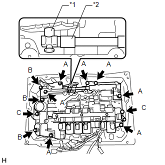
3. INSTALL TRANSMISSION VALVE BODY ASSEMBLY
|
(a) Insert the manual valve lever sub-assembly into the groove on the end of the manual valve and install the transmission valve body assembly to the automatic transmission case sub-assembly with the 12 bolts. Text in Illustration
Torque: 11 N·m {112 kgf·cm, 8 ft·lbf} HINT: Bolt length:
|
|
(b) Install the detent spring and detent spring cover to the transmission valve body assembly with the bolt.
Torque:
10 N·m {102 kgf·cm, 7 ft·lbf}
4. INSTALL VALVE BODY OIL STRAINER ASSEMBLY
(a) Coat a new O-ring with ATF, and install it to the valve body oil strainer assembly.
(b) Install the valve body oil strainer assembly to the transmission valve body assembly with the 3 bolts.
Torque:
10 N·m {102 kgf·cm, 7 ft·lbf}
5. CONNECT TRANSMISSION WIRE
(See page .gif) )
)
6. CHECK AUTOMATIC TRANSMISSION SYSTEM
(See page )
 Reassembly
REASSEMBLY
PROCEDURE
1. INSTALL SHIFT SOLENOID VALVE SLT
(a) Install the shift solenoid valve SLT and straight pin to the transmission
valve body assembly.
...
 Axle
Axle
...
Other materials:
Disposal
DISPOSAL
PROCEDURE
1. DISPOSE OF BRAKE BOOSTER ACCUMULATOR ASSEMBLY
(a) Place the brake booster accumulator in a vise and cover it with a cloth.
(b) Slowly cut a hole on the brake booster accumulator side in the A portion
shown in the illustration on the left. And discharge the gas and liqui ...
Diagnosis System
DIAGNOSIS SYSTEM
CHECK DLC3
(a) Check the DLC3.
Click here
FUNCTION OF WARNING INDICATOR AND MESSAGE
(a) If the lane departure alert system is not functioning properly, the driver
is warned by the lane departure alert indicator and multi-information display warning
message on the combinat ...
Stereo Component Amplifier Malfunction (B15A3)
DESCRIPTION
This DTC is stored when a malfunction occurs in the stereo component amplifier
assembly.
DTC No.
DTC Detection Condition
Trouble Area
B15A3
When one of the conditions below is met:
Internal power supply malfun ...
