Toyota Tacoma (2015-2018) Service Manual: Inspection
INSPECTION
PROCEDURE
1. INSPECT CAMSHAFT TIMING OIL CONTROL SOLENOID ASSEMBLY
(a) Check the operation.
|
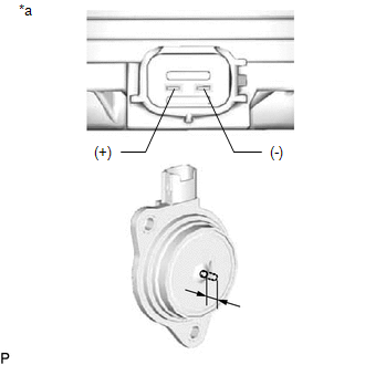
(1) Apply battery voltage between the terminals and check that the plunger operates. Text in Illustration
OK: The plunger extends outwards 5.9 mm (0.232 in.) or more. If the result is not as specified, replace the camshaft timing oil control solenoid assembly. |
|
 On-vehicle Inspection
ON-VEHICLE INSPECTION
PROCEDURE
1. INSPECT CAMSHAFT TIMING OIL CONTROL SOLENOID ASSEMBLY (for Intake Side)
(a) Connect the Techstream to the DLC3.
(b) Start the engine.
(c) Turn the Techstream on ...
 Removal
REMOVAL
PROCEDURE
1. REMOVE FRONT FENDER SEAL RH
HINT:
Use the same procedure as for the LH side (See page
).
2. REMOVE V-BANK COVER SUB-ASSEMBLY
3. REMOVE AIR CLEANER CAP AND HOSE
4. ...
Other materials:
Removal
REMOVAL
CAUTION / NOTICE / HINT
HINT:
Use the same procedure for the RH side and LH side.
The following procedure is for the LH side.
PROCEDURE
1. PRECAUTION
NOTICE:
After turning the ignition switch off, waiting time may be required before disconnecting
the cable from the ...
Output Speed Sensor Circuit No Signal (P0722,P077C,P077D)
DESCRIPTION
This sensor detects the rotation speed of the transmission output shaft and sends
signals to the ECM. By comparing the input turbine speed signal (NT) with the output
shaft speed sensor signal (SP2), the ECM detects the shift timing of the gears and
appropriately controls the engi ...
Starter Relay Circuit Short to Battery (P061512)
DESCRIPTION
While the engine is being cranked, positive battery voltage is applied to terminal
STA of the ECM. If the ECM detects the starter control (STA) signal while the vehicle
is being driven, it determines that there is a malfunction in the STA circuit. The
ECM then illuminates the MIL ...
