Toyota Tacoma (2015-2018) Service Manual: Mirror Heater does not Operate with Rear Defogger Switch
DESCRIPTION
When the mirror heater switch on the air conditioning control assembly is pressed, the operation signal is sent to the air conditioning amplifier assembly. When the air conditioning amplifier assembly receives the signal, it turns on a relay in the air conditioning amplifier assembly to operate the mirror heaters.
WIRING DIAGRAM
See page ( .gif) ).
).
CAUTION / NOTICE / HINT
NOTICE:
Inspect the fuses for circuits related to this system before performing the following procedure.
PROCEDURE
|
1. |
PERFORM ACTIVE TEST USING TECHSTREAM |
(a) Connect the Techstream to the DLC3.
(b) Turn the ignition switch to ON.
(c) Turn the Techstream on.
(d) Enter the following menus: Body Electrical / Air Conditioner / Active Test.
(e) Perform the Active Test according to the display on the Techstream.
Air Conditioner|
Tester Display |
Measurement Item |
Control Range |
Diagnostic Note |
|---|---|---|---|
|
Defogger Relay (Rear) |
Mirror heater operation |
OFF or ON |
- |
|
Result |
Proceed to |
|---|---|
|
Mirror heater operation on both mirrors is not normal |
A |
|
Mirror heater operation on RH side mirror is not normal |
B |
|
Mirror heater operation on LH side mirror is not normal |
C |
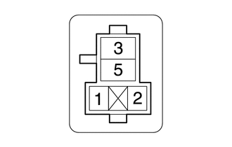
| B | .gif) |
GO TO STEP 7 |
| C | |
GO TO STEP 9 |
|
.gif)
|
2. |
INSPECT MIR HTR RELAY |
|
(a) Remove the MIR HTR relay from the instrument panel relay block. |
|
(b) Measure the resistance according to the value(s) in the table below.
Standard Resistance:
|
Tester Connection |
Condition |
Specified Condition |
|---|---|---|
|
3 - 5 |
Battery voltage applied to terminals 1 and 2 |
Below 1 Ω |
|
3 - 5 |
Battery voltage not applied between terminals |
10 kΩ or higher |
| NG | |
REPLACE MIR HTR RELAY |
|
|
3. |
CHECK HARNESS AND CONNECTOR (MIR HTR RELAY - AIR CONDITIONING AMPLIFIER ASSEMBLY) |
(a) for Automatic Air Conditioning
(1) Disconnect the A35 air conditioning amplifier assembly connector.
(2) Measure the resistance according to the value(s) in the table below.
Standard Resistance:
|
Tester Connection |
Condition |
Specified Condition |
|---|---|---|
|
MHR HTR relay terminal 1 - A35-9 (MHTR) |
Always |
Below 1 Ω |
|
MHR HTR relay terminal 1 or A35-9 (MHTR) - Body ground |
Always |
10 kΩ or higher |
(b) for Manual Air Conditioning
(1) Disconnect the A14 air conditioning amplifier assembly connector.
(2) Measure the resistance according to the value(s) in the table below.
Standard Resistance:
|
Tester Connection |
Condition |
Specified Condition |
|---|---|---|
|
MHR HTR relay terminal 1 - A14-17 (MHTR) |
Always |
Below 1 Ω |
|
MHR HTR relay terminal 1 or A14 -17 (MHTR) - Body ground |
Always |
10 kΩ or higher |
| NG | |
REPAIR OR REPLACE HARNESS OR CONNECTOR |
|
|
4. |
CHECK HARNESS AND CONNECTOR (AIR CONDITIONING AMPLIFIER ASSEMBLY - AIR CONDITIONING CONTROL ASSEMBLY) |
(a) for Automatic Air Conditioning
(1) Disconnect the A36 air conditioning amplifier assembly connector.
(2) Disconnect the A33 air conditioning control assembly connector.
(3) Measure the resistance according to the value(s) in the table below.
Standard Resistance:
|
Tester Connection |
Condition |
Specified Condition |
|---|---|---|
|
A33-10(E) - A36-5 (RDSW) |
Always |
Below 1 Ω |
|
A33-10(E) or A36-5 (RDSW) - Body ground |
Always |
10 kΩ or higher |
(b) for Manual Air Conditioning
(1) Disconnect the A14 air conditioning amplifier assembly connector.
(2) Disconnect the A33 air conditioning control assembly connector.
(3) Measure the resistance according to the value(s) in the table below.
Standard Resistance:
|
Tester Connection |
Condition |
Specified Condition |
|---|---|---|
|
A33-15(E) - A14-29 (RDSW) |
Always |
Below 1 Ω |
|
A33-15(E) or A14-29 (RDSW) - Body ground |
Always |
10 kΩ or higher |
| NG | |
REPAIR OR REPLACE HARNESS OR CONNECTOR |
|
|
5. |
REPLACE AIR CONDITIONING CONTROL ASSEMBLY |
(a) Replace the air conditioning control assembly.
- for Automatic Air Conditioning (See page
)
- for Manual Air Conditioning (See page
)
|
|
6. |
CHECK MIRROR HEATER OPERATION |
(a) Check the mirror heater operation.
(See page )
| OK | |
END (AIR CONDITIONING CONTROL ASSEMBLY WAS DEFECTIVE) |
| NG | |
REPLACE AIR CONDITIONING AMPLIFIER ASSEMBLY |
|
7. |
CHECK HARNESS AND CONNECTOR (MIR HTR RELAY - OUTER REAR VIEW MIRROR ASSEMBLY RH - BODY GROUND) |
(a) Remove the MIR HTR relay from the instrument panel relay block.
(b) Disconnect the O3 outer rear view mirror assembly RH connector.
(c) Measure the resistance according to the value(s) in the table below.
Standard Resistance:
|
Tester Connection |
Condition |
Specified Condition |
|---|---|---|
|
MIR HTR relay terminal 3 - O3-2 (+) |
Always |
Below 1 Ω |
|
O3-8 (-) - Body Ground |
Always |
Below 1 Ω |
|
MIR HTR relay terminal 3 or O3-2 (+) - Body Ground |
Always |
10 kΩ or higher |
|
Proceed to |
|---|
|
OK |
|
NG |
| NG | |
REPAIR OR REPLACE HARNESS OR CONNECTOR |
|
|
8. |
INSPECT OUTER MIRROR COVER RH (MIRROR HEATER) |
(a) Remove the outer mirror RH.
(See page )
(b) Inspect the outer mirror RH.
(See page )
OK:
Outer mirror RH is normal.
Result|
Proceed to |
|---|
|
OK |
|
NG |
| OK | |
REPLACE OUTER REAR VIEW MIRROR ASSEMBLY RH |
| NG | |
REPLACE OUTER MIRROR RH |
|
9. |
CHECK HARNESS AND CONNECTOR (MIR HTR RELAY - OUTER REAR VIEW MIRROR ASSEMBLY LH - BODY GROUND) |
(a) Remove the MIR HTR relay from the instrument panel relay block.
(b) Disconnect the O2 outer rear view mirror assembly LH connector.
(c) Measure the resistance according to the value(s) in the table below.
Standard Resistance:
|
Tester Connection |
Condition |
Specified Condition |
|---|---|---|
|
MIR HTR relay terminal 3 - O2-2 (+) |
Always |
Below 1 Ω |
|
O2-8 (-) - Body Ground |
Always |
Below 1 Ω |
|
MIR HTR relay terminal 3 or O2-2 (+) - Body Ground |
Always |
10 kΩ or higher |
|
Proceed to |
|---|
|
OK |
|
NG |
| NG | |
REPAIR OR REPLACE HARNESS OR CONNECTOR |
|
|
10. |
INSPECT OUTER MIRROR COVER LH (MIRROR HEATER) |
(a) Remove the outer mirror LH.
(See page )
(b) Inspect the outer mirror LH.
(See page )
OK:
Outer mirror LH is normal.
Result|
Proceed to |
|---|
|
OK |
|
NG |
| OK | |
REPLACE OUTER REAR VIEW MIRROR ASSEMBLY LH |
| NG | |
REPLACE OUTER MIRROR LH |
 Diagnosis System
DIAGNOSIS SYSTEM
1. CHECK DLC3
(a) Check the DLC3 (See page ).
2. INSPECT BATTERY VOLTAGE
(a) Measure the battery voltage.
Standard voltage:
11 to 14 V
If the voltage is below 11 V, recharge ...
 Other System
...
Other materials:
Headlight Dimmer Relay
Inspection
INSPECTION
PROCEDURE
1. INSPECT HEADLIGHT DIMMER RELAY
(a) Check the resistance.
(1) Measure the resistance according to the value(s) in the table below.
Standard:
Tester Connection
Condition
Specified Condition
...
Diagnosis System
DIAGNOSIS SYSTEM
1. DESCRIPTION
(a) When troubleshooting a vehicle with a diagnosis system, the only difference
from the usual troubleshooting procedure is connecting the Techstream to the vehicle
and reading various data output from the clearance warning ECU assembly.
The clearance warning E ...
Navigation Receiver Assembly Communication Stop Mode
DESCRIPTION
Detection Item
Symptom
Trouble Area
Navigation Receiver Assembly Communication Stop Mode
Either condition is met:
Communication stop for "Display and Navigation (AVN1)" is indicated
on the "C ...
