Toyota Tacoma (2015-2018) Service Manual: Terminals Of Ecu
TERMINALS OF ECU
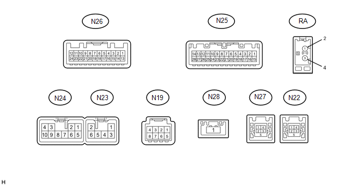
1. NAVIGATION RECEIVER ASSEMBLY
|
Terminal No. (Symbols) |
Wiring Color |
Terminal Description |
Condition |
Specified Condition |
|---|---|---|---|---|
|
N19-3 (ACC2) - N24-7 (GND1)*3 |
Y - W-B |
Power source (ACC) |
Ignition switch off |
Below 1 V |
|
Ignition switch ACC |
11 to 14 V |
|||
|
N19-4 (+B2) - N24-7 (GND1)*3 |
R - W-B |
Power source (+B) |
Always |
11 to 14 V |
|
N19-8 (GND2) - Body ground*3 |
B - Body ground |
Ground |
Always |
Below 1 V |
|
N22-1 (UPO) |
- |
Power source |
- |
- |
|
N22-2 (UDO-) |
- |
Data signal |
- |
- |
|
N22-3 (UDO+) |
- |
Data signal |
- |
- |
|
N22-4 (UESG) |
- |
Ground |
- |
- |
|
N23-1 (RR+) - N24-7 (GND1)*5 |
L - W-B |
Sound signal (Rear) |
Audio system playing |
A waveform synchronized with sounds is output |
|
N23-2 (RL+) - N24-7 (GND1)*5 |
W - W-B |
Sound signal (Rear) |
Audio system playing |
A waveform synchronized with sounds is output |
|
N23-3 (RR-) - N24-7 (GND1)*5 |
LG - W-B |
Sound signal (Rear) |
Audio system playing |
A waveform synchronized with sounds is output |
|
N23-4 (SLD2) - N24-7 (GND1)*1 |
Shielded - W-B |
Shield ground |
Always |
Below 1 V |
|
N23-5 (ILL-) - N24-7 (GND1) |
BE - W-B |
Illumination signal |
Light control switch off |
Below 1 V |
|
Light control switch in tail or head position |
Pulse generation |
|||
|
N23-6 (RL-) - N24-7 (GND1)*5 |
B - W-B |
Sound signal (Rear) |
Audio system playing |
A waveform synchronized with sounds is output |
|
N24-1 (FR+) - N24-7 (GND1) |
R - W-B*1 LA-R - W-B*2 |
Sound signal (Right) |
Audio system playing |
A waveform synchronized with sounds is output |
|
N24-2 (FL+) - N24-7 (GND1) |
B - W-B*1 LA-B - W-B*2 |
Sound signal (Left) |
Audio system playing |
A waveform synchronized with sounds is output |
|
N24-3 (ACC1) - N24-7 (GND1) |
GR - W-B |
Power source (ACC) |
Ignition switch off |
Below 1 V |
|
Ignition switch ACC |
11 to 14 V |
|||
|
N24-4 (+B1) - N24-7 (GND1) |
W - W-B |
Power source (+B) |
Always |
11 to 14 V |
|
N24-5 (FR-) - N24-7 (GND1) |
G - W-B*1 LA-G - W-B*2 |
Sound signal (Right) |
Audio system playing |
A waveform synchronized with sounds is output |
|
N24-6 (FL-) - N24-7 (GND1) |
W - W-B*1 LA-W - W-B*2 |
Sound signal (Left) |
Audio system playing |
A waveform synchronized with sounds is output |
|
N24-7 (GND1) - Body ground |
W-B - Body ground |
Ground |
Always |
Below 1 V |
|
N24-10 (ILL+) - N24-7 (GND1) |
G - W-B |
Illumination signal |
Light control switch off |
Below 1 V |
|
Light control switch in tail or head position |
11 to 14 V |
|||
|
N25-1 (IG) - N24-7 (GND1) |
LG - W-B |
Power source (IG) |
Ignition switch off |
Below 1 V |
|
Ignition switch ON |
11 to 14 V |
|||
|
N25-2 (REV) - N24-7 (GND1) |
GR - W-B |
Reverse signal |
See "Vehicle Signal Check Mode" in Operation Check (See page
|
- |
|
N25-4 (MACC) - N24-7 (GND1) |
R - W-B |
Microphone power supply |
Ignition switch off |
Below 1 V |
|
Ignition switch ACC |
4 to 6 V |
|||
|
N25-5 (MIN+) - N24-7 (GND1) |
G - W-B |
Microphone voice signal |
See "Microphone Level Test" in Operation Check (See page
|
- |
|
N25-6 (SNS2) - N24-7 (GND1) |
W - W-B |
Microphone connection detection signal |
Always |
Below 1 V |
|
N25-7 (TX1+)*1 |
BE |
AVC-LAN communication signal |
- |
- |
|
N25-8 (TX1-)*1 |
P |
AVC-LAN communication signal |
- |
- |
|
N25-11 (AGND) - N24-7 (GND1) |
Shielded - W-B |
Shield ground |
Always |
Below 1 V |
|
N25-15 (PKB) - N24-7 (GND1) |
Y - W-B |
Parking brake signal |
See "Vehicle Signal Check Mode" in Operation Check (See page
|
- |
|
N25-16 (MUT1) - N24-7 (GND1)*1 |
SB - W-B |
Mute signal |
Audio system playing |
Above 3.5 V |
|
Audio system changing modes |
Below 1 V |
|||
|
N25-17 (SPD) - N24-7 (GND1) |
V - W-B |
Vehicle speed signal |
See "Vehicle Signal Check Mode" in Operation Check (See page
|
- |
|
N25-18 (SGND) - N24-7 (GND1) |
Shielded - W-B |
Shield ground |
Always |
Below 1 V |
|
N25-19 (MIN-) - N24-7 (GND1) |
B - W-B |
Microphone voice signal |
See "Microphone Level Test" in Operation Check (See page
|
- |
|
N25-21 (SW1) - N25-23 (SWG) |
V - SB |
Steering pad switch signal |
No switch pushed |
2.97 to 3.56 V |
|
Up switch pushed |
0.27 to 0.35 V |
|||
|
Down switch pushed |
0.86 to 1.03 V |
|||
|
Volume+ switch pushed |
1.51 to 1.79 V |
|||
|
Volume- switch pushed |
2.22 to 2.66 V |
|||
|
N25-22 (SW2) - N25-23 (SWG) |
Y - SB |
Steering pad switch signal |
No switch pushed |
2.97 to 3.56 V |
|
MODE/HOLD switch pushed |
0.27 to 0.35 V |
|||
|
On hook switch pushed |
0.86 to 1.03 V |
|||
|
Off hook switch pushed |
1.51 to 1.79 V |
|||
|
Voice switch pushed |
2.22 to 2.66 V |
|||
|
N25-23 (SWG) - N24-7 (GND1) |
SB - W-B |
Steering pad switch ground |
Always |
Below 1 V |
|
N25-25 (ADPG) - N24-7 (GND1) |
W-B - W-B |
External device connection detection signal |
External device connected |
Below 1 V |
|
N25-26 (VAR+) - N24-7 (GND1) |
W - W-B |
Sound signal (Right) |
External device playing (When stereo jack used) |
A waveform synchronized with sounds is output |
|
N25-27 (VA-) - N24-7 (GND1) |
R - W-B |
Ground |
Always |
Below 1 V |
|
N25-28 (VAL+) - N24-7 (GND1) |
B - W-B |
Sound signal (Left) |
External device playing (When stereo jack used) |
A waveform synchronized with sounds is output |
|
N26-3 (CNH1) |
B |
Local bus communication signal |
- |
- |
|
N26-4 (CNL1) |
W |
Local bus communication signal |
- |
- |
|
N26-11 (CA+) - N24-7 (GND1)*4 |
B - W-B |
Power source |
Ignition switch ACC |
5.5 to 7.05 V |
|
N26-12 (V+) - N26-24 (V-)*4 |
R - W |
Display signal |
Ignition switch ON, shift lever in R |
Pulse generation (See waveform 1) |
|
Ignition switch ON, shift lever in R, screen blacked out by covering camera lens |
Pulse generation (See waveform 2) |
|||
|
N26-23 (CGND) - N24-7 (GND1)*4 |
Shielded - W-B |
Shield ground |
Always |
Below 1 V |
|
N27-1 (USV4)*3 |
- |
Power source |
- |
- |
|
N27-2 (US4-)*3 |
- |
Data signal |
- |
- |
|
N27-3 (US4+)*3 |
- |
Data signal |
- |
- |
|
N27-4 (UGO4)*3 |
- |
Ground |
- |
- |
|
N27-5 (USG4)*3 |
- |
Shield ground |
- |
- |
|
N28-1 (LVDS) - N24-7 (GND1)*3 |
B - W-B |
LVDS communication signal |
- |
- |
|
RA-5 (ANT+) - N24-7 (GND1) |
- - W-B |
Power source of antenna |
Ignition switch ACC Radio switch on and FM or AM selected |
11 to 14 V |
.gif) )
)- *1: w/ Stereo Component Amplifier
- *2: w/o Stereo Component Amplifier
- *3: w/ SDARS System
- *4: w/ Rear Television Camera
- *5: for 6 Speakers
(a) Using an oscilloscope, check the waveform.
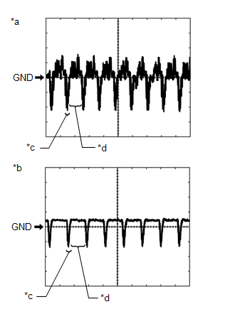
(1) Waveform 1
Measurement Condition|
Item |
Content |
|---|---|
|
Terminal No. (Symbol) |
N26-12 (V+) - N26-24 (V-) |
|
Tool Setting |
0.2 V/DIV., 50 ÎĽs./DIV. |
|
Condition |
Ignition switch ON, shift lever in R |
HINT:
The video waveform changes according to the image sent by the television camera assembly.
(2) Waveform 2
Measurement Condition|
Item |
Content |
|---|---|
|
Terminal No. (Symbol) |
N26-12 (V+) - N26-24 (V-) |
|
Tool Setting |
0.2 V/DIV., 50 ÎĽs./DIV. |
|
Condition |
Ignition switch ON, shift lever in R, screen blacked out by covering camera lens |
HINT:
The video waveform changes according to the image sent by the television camera assembly.
Text in Illustration|
*a |
Waveform 1 |
|
*b |
Waveform 2 |
|
*c |
Synchronized Signal |
|
*d |
Video Waveform |
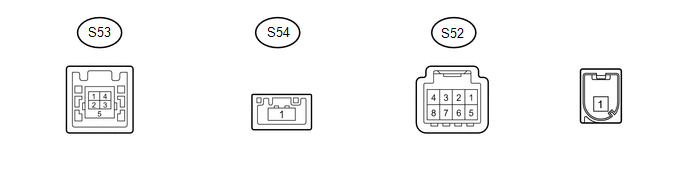
2. STEREO COMPONENT TUNER ASSEMBLY (w/ SDARS System)
|
Terminal No. (Symbols) |
Wiring Color |
Terminal Description |
Condition |
Specified Condition |
|---|---|---|---|---|
|
S52-3 (ACC2) - S52-8 (GND2) |
Y - B |
Power source (ACC) |
Ignition switch off |
Below 1 V |
|
Ignition switch ACC |
11 to 14 V |
|||
|
S52-4 (+B2) - S52-8 (GND2) |
R - B |
Power source (+B) |
Always |
11 to 14 V |
|
S52-8 (GND2) - Body ground |
B - Body ground |
Ground |
Always |
Below 1 V |
|
S53-1 (USV4) |
- |
Power source |
- |
- |
|
S53-2 (US4-) |
- |
Data signal |
- |
- |
|
S53-3 (US4+) |
- |
Data signal |
- |
- |
|
S53-4 (UGO4) |
- |
Ground |
- |
- |
|
S53-5 (USG4) |
Shielded |
Shield ground |
- |
- |
|
S54-1 (LVDS) |
B |
LVDS communication signal |
- |
- |
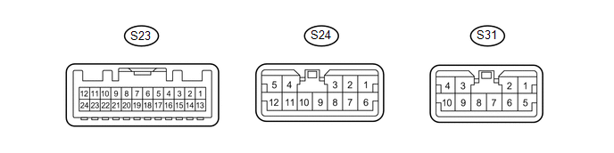
3. STEREO COMPONENT AMPLIFIER ASSEMBLY (w/ Stereo Component Amplifier)
|
Terminal No. (Symbol) |
Wiring Color |
Terminal Description |
Condition |
Specified Condition |
|---|---|---|---|---|
|
S23-1 (MUTE) - S24-6 (GND) |
SB - W-B |
Mute signal |
Audio system is playing |
Above 3.5 V |
|
Audio system is changing mode |
Below 1 V |
|||
|
S23-2 (L-) - S24-6 (GND) |
W - W-B |
Sound signal (Left) |
Audio system is playing |
A waveform synchronized with sounds is output |
|
S23-3 (L+) - S24-6 (GND) |
B - W-B |
Sound signal (Left) |
Audio system is playing |
A waveform synchronized with sounds is output |
|
S23-4 (R-) - S24-6 (GND) |
G - W-B |
Sound signal (Right) |
Audio system is playing |
A waveform synchronized with sounds is output |
|
S23-5 (R+) - S24-6 (GND) |
R - W-B |
Sound signal (Right) |
Audio system is playing |
A waveform synchronized with sounds is output |
|
S23-6 (SGND) - Body ground |
Shielded - Body ground |
Shield ground |
Always |
Below 1 V |
|
S23-7 (TX-) |
P |
AVC-LAN communication signal |
- |
- |
|
S23-8 (TX+) |
BE |
AVC-LAN communication signal |
- |
- |
|
S23-11 (SPD) - S24-6 (GND) |
V - W-B |
Vehicle speed signal |
Ignition switch ON, drive wheels turned slowly |
Pulse generation |
|
S23-12 (ACC) - S24-6 (GND) |
GR - W-B |
Power source (ACC) |
Ignition switch off |
Below 1 V |
|
Ignition switch ACC |
11 to 14 V |
|||
|
S23-22 (INT-) - S24-6 (GND) |
B - W-B |
Voice signal |
Voice guidance sounding |
A waveform synchronized with sounds is output |
|
S23-23 (INT+) - S24-6 (GND) |
W - W-B |
Voice signal |
Voice guidance sounding |
A waveform synchronized with sounds is output |
|
S24-1 (FL-) - S24-6 (GND) |
LG - W-B |
Sound signal (Front Left) |
Audio system is playing |
A waveform synchronized with sounds is output |
|
S24-2 (FL+) - S24-6 (GND) |
G - W-B |
Sound signal (Front Left) |
Audio system is playing |
A waveform synchronized with sounds is output |
|
S24-3 (FR-) - S24-6 (GND) |
L - W-B |
Sound signal (Front Right) |
Audio system is playing |
A waveform synchronized with sounds is output |
|
S24-4 (WFR+) - S24-6 (GND) |
LA-B - W-B |
Sound signal (Woofer) |
Audio system is playing |
A waveform synchronized with sounds is output |
|
S24-5 (WFL+) - S24-6 (GND) |
LA-G - W-B |
Sound signal (Woofer) |
Audio system is playing |
A waveform synchronized with sounds is output |
|
S24-6 (GND) - Body ground |
W-B - Body ground |
Ground |
Always |
Below 1 V |
|
S24-7 (E) - Body ground |
W-B - Body ground |
Ground |
Always |
Below 1 V |
|
S24-9 (FR+) - S24-6 (GND) |
GR - W-B |
Sound signal (Front Right) |
Audio system is playing |
A waveform synchronized with sounds is output |
|
S24-10 (WFR-) - S24-6 (GND) |
LA-R - W-B |
Sound signal (Woofer) |
Audio system is playing |
A waveform synchronized with sounds is output |
|
S24-12 (WFL-) - S24-6 (GND) |
LA-Y - W-B |
Sound signal (Woofer) |
Audio system is playing |
A waveform synchronized with sounds is output |
|
S31-1 (+B) - S24-6 (GND) |
W - W-B |
Power source (+B) |
Always |
11 to 14 V |
|
S31-2 (TWR+) - S24-6 (GND) |
P - W-B |
Sound signal (Front Right) |
Audio system is playing |
A waveform synchronized with sounds is output |
|
S31-3 (RL+) - S24-6 (GND) |
W - W-B |
Sound signal (Rear Left) |
Audio system is playing |
A waveform synchronized with sounds is output |
|
S31-4 (RR-) - S24-6 (GND) |
LA-LG - W-B |
Sound signal (Rear Right) |
Audio system is playing |
A waveform synchronized with sounds is output |
|
S31-5 (+B2) - S24-6 (GND) |
SB - W-B |
Power source (+B) |
Always |
11 to 14 V |
|
S31-6 (TWR-) - S24-6 (GND) |
V - W-B |
Sound signal (Front Right) |
Audio system is playing |
A waveform synchronized with sounds is output |
|
S31-7 (TWL-) - S24-6 (GND) |
R - W-B |
Sound signal (Front Left) |
Audio system is playing |
A waveform synchronized with sounds is output |
|
S31-8 (TWL+) - S24-6 (GND) |
Y - W-B |
Sound signal (Front Left) |
Audio system is playing |
A waveform synchronized with sounds is output |
|
S31-9 (RL-) - S24-6 (GND) |
B - W-B |
Sound signal (Rear Left) |
Audio system is playing |
A waveform synchronized with sounds is output |
|
S31-10 (RR+) - S24-6 (GND) |
LA-L - W-B |
Sound signal (Rear Right) |
Audio system is playing |
A waveform synchronized with sounds is output |
 Problem Symptoms Table
PROBLEM SYMPTOMS TABLE
NOTICE:
After replacing the stereo component tuner assembly of vehicles subscribed
to pay-type satellite radio broadcasts, XM radio ID registration is necessary
...
 Dtc Check / Clear
DTC CHECK / CLEAR
1. START DIAGNOSTIC MODE
HINT:
Illustrations may differ from the actual vehicle screen depending on
the device settings and options. Therefore, some detailed areas may ...
Other materials:
Installation
INSTALLATION
PROCEDURE
1. INSTALL REAR SEATBACK CENTER HINGE SUB-ASSEMBLY
(a) Install the rear seatback center hinge sub-assembly with the 2 bolts.
Torque:
30 N·m {306 kgf·cm, 22 ft·lbf}
2. INSTALL LUGGAGE COMPARTMENT SIDE TRAY
3. INSTALL REAR SEATBACK HINGE SUB-ASSEMBLY
(a) Install ...
Intake Air Control Valve Actuator(for Acis)
Components
COMPONENTS
ILLUSTRATION
Inspection
INSPECTION
PROCEDURE
1. INSPECT INTAKE AIR CONTROL VALVE ACTUATOR
(a) Check the operate.
(1) Apply battery voltage to the connector, and check the operation of
the intake air control valve actuator gear.
Text in Illustrati ...
Components
COMPONENTS
ILLUSTRATION
ILLUSTRATION
ILLUSTRATION
ILLUSTRATION
ILLUSTRATION
...
