Toyota Tacoma (2015-2018) Service Manual: Inspection
INSPECTION
PROCEDURE
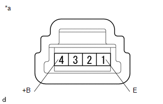
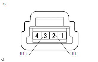
1. INSPECT AUTO HIGH BEAM SWITCH
|
*a |
Component without harness connected (Auto High Beam Switch) |
(a) Check the resistance.
(1) Measure the resistance according to the value(s) in the table below.
Standard Resistance:
|
Tester Connection |
Switch Condition |
Specified Condition |
|---|---|---|
| If the result is not as specified, replace the auto high beam switch. | ||
|
4 (+B) - 1 (E) |
Auto high beam switch ON |
Below 1 Ω |
|
Auto high beam switch OFF |
10 kΩ or higher |
|
|
(b) Check the illumination. (1) Apply battery voltage to the connector and check the illumination condition. OK:
|
|
||||||||||
 Components
COMPONENTS
ILLUSTRATION
*A
for Double Cab
*B
for Access Cab
*1
AUTO HIGH BEAM SWITCH
*2
COWL SIDE TRIM ...
 Removal
REMOVAL
PROCEDURE
1. REMOVE FRONT DOOR SCUFF PLATE LH
for Double Cab:
Click here
for Access Cab:
Click here
2. REMOVE COWL SIDE TRIM BOARD LH
Click here
3. REMOVE INSTRUMENT CLUSTER CEN ...
Other materials:
Terminals Of Ecu
TERMINALS OF ECU
1. CHECK MAIN BODY ECU (MULTIPLEX NETWORK BODY ECU)
(a) Disconnect the 1D and 1F driver side junction block connectors.
(b) Measure the voltage and resistance according to the value(s) in the table
below.
HINT:
Measure the values on the wire harness side with the connectors ...
CD cannot be Inserted / Played or CD is Ejected Right After Insertion
PROCEDURE
1.
CHECK IF A PROPER CD IS INSERTED
(a) Make sure that the CD is an audio CD or a CD with an MP3, WMA or AAC file,
and that it is not deformed, flawed, stained, deteriorated or otherwise defective.
OK:
CD is normal.
HINT:
Translucent or uniq ...
Stereo Component Amplifier Malfunction (B15A3)
DESCRIPTION
This DTC is stored when a malfunction occurs in the stereo component amplifier
assembly.
DTC No.
DTC Detection Condition
Trouble Area
B15A3
When one of the conditions below is met:
Internal power supply malfun ...
