Toyota Tacoma (2015-2018) Service Manual: Components
COMPONENTS
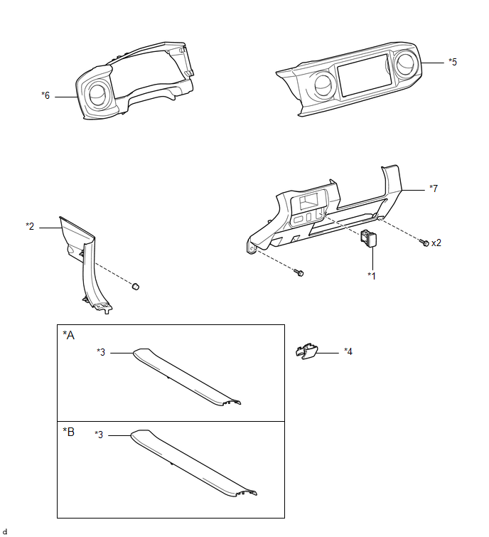
ILLUSTRATION
|
*A |
for Double Cab |
*B |
for Access Cab |
|
*1 |
AUTO HIGH BEAM SWITCH |
*2 |
COWL SIDE TRIM BOARD LH |
|
*3 |
FRONT DOOR SCUFF PLATE LH |
*4 |
HOOD LOCK CONTROL LEVER SUB-ASSEMBLY |
|
*5 |
INSTRUMENT CLUSTER CENTER FINISH PANEL SUB-ASSEMBLY |
*6 |
INSTRUMENT CLUSTER FINISH PANEL ASSEMBLY |
|
*7 |
INSTRUMENT PANEL LOWER FINISH PANEL SUB-ASSEMBLY |
- |
- |

 Inspection
INSPECTION
PROCEDURE
1. INSPECT AUTO HIGH BEAM SWITCH
*a
Component without harness connected
(Auto High Beam Switch)
(a) Check the resistance.
(1) Measure the ...
Other materials:
Reassembly
REASSEMBLY
PROCEDURE
1. INSPECT CENTER NO. 2 SUPPORT BEARING ASSEMBLY
(a) Turn the center bearing by hand, check that it turns smoothly without catching
and that there are no cracks or damage.
If there are any defects, replace it.
2. INSTALL CENTER NO. 2 SUPPORT BEARING ASSEMBLY
(a) Instal ...
Precaution
PRECAUTION
1. IGNITION SWITCH EXPRESSIONS
(a) The type of ignition switch used on this model differs according to the specifications
of the vehicle. The expressions listed in the table below are used in this section.
Expression
Ignition Switch (Position)
Engine ...
Evaporator Temperature Sensor Circuit (B1413)
DESCRIPTION
The cooler thermistor sensor (evaporator temperature sensor) is installed on
the evaporator in the air conditioner unit to detect the temperature of the cooled
air that has passed through the evaporator and is used to control the air conditioning.
It sends signals to the air condi ...
