Toyota Tacoma (2015-2018) Service Manual: Fuel Pressure Sensor
Components
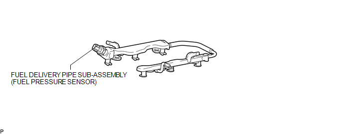
COMPONENTS
ILLUSTRATION
Inspection
INSPECTION
PROCEDURE
1. INSPECT FUEL DELIVERY PIPE SUB-ASSEMBLY (FUEL PRESSURE SENSOR)
NOTICE:
- Do not remove the fuel pressure sensor from the fuel delivery pipe sub-assembly.
- If a fuel pressure sensor is removed, replace the fuel delivery pipe sub-assembly with a new one.
(a) Remove the fuel delivery pipe sub-assembly (See page
.gif) ).
).
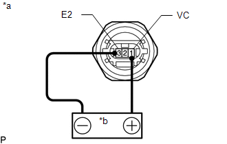
(b) Check the fuel pressure sensor output voltage.
|
(1) Apply 5 V between terminals 1 (VC) and 3 (E2). Text in Illustration
NOTICE:
HINT: If a stable power supply is not available, use 4 1.2 V nickel-metal hydride batteries or equivalent. |
|
|
(2) Measure the voltage between terminals. Text in Illustration
Standard Voltage:
If the result is not as specified, replace the fuel delivery pipe sub-assembly. |
|
(c) Install the fuel delivery pipe sub-assembly (See page
).
Installation
INSTALLATION
CAUTION / NOTICE / HINT
HINT:
Perform "Inspection After Repairs" after replacing the fuel delivery pipe sub-assembly
(fuel pressure sensor) (See page .gif) ).
).
PROCEDURE
1. INSTALL FUEL DELIVERY PIPE SUB-ASSEMBLY (FUEL PRESSURE SENSOR)
(See page )
NOTICE:
- Do not remove the fuel pressure sensor from the fuel delivery pipe sub-assembly.
- If a fuel pressure sensor is removed, replace the fuel delivery pipe sub-assembly (fuel pressure sensor) with a new one.
HINT:
Perform "Inspection After Repairs" after replacing the fuel delivery pipe sub-assembly
(fuel pressure sensor) (See page ).
Removal
REMOVAL
PROCEDURE
1. REMOVE FUEL DELIVERY PIPE SUB-ASSEMBLY (FUEL PRESSURE SENSOR)
(See page .gif) )
)
NOTICE:
- Do not remove the fuel pressure sensor from the fuel delivery pipe sub-assembly.
- If a fuel pressure sensor is removed, replace the fuel delivery pipe sub-assembly (fuel pressure sensor) with a new one.
 Fuel Main Valve
Components
COMPONENTS
ILLUSTRATION
Removal
REMOVAL
PROCEDURE
1. REMOVE FUEL SUCTION TUBE WITH PUMP AND GAUGE ASSEMBLY
(See page )
2. REMOVE FUEL SENDER GAUGE ASSEMBLY
3. REMOVE NO. ...

Other materials:
Back-up Light Switch
Components
COMPONENTS
ILLUSTRATION
Inspection
INSPECTION
PROCEDURE
1. INSPECT BACK-UP LIGHT SWITCH ASSEMBLY
(a) Measure the resistance according to the value(s) in the table below.
Text in Illustration
*a
Pushed
...
CD cannot be Inserted / Played or CD is Ejected Right After Insertion
PROCEDURE
1.
CHECK IF A PROPER CD IS INSERTED
(a) Make sure that the CD is an audio CD or a CD with an MP3, WMA or AAC file,
and that it is not deformed, flawed, stained, deteriorated or otherwise defective.
OK:
CD is normal.
HINT:
Translucent or uniq ...
Overhead console (Access Cab and Double Cab models)
The overhead console is useful for temporarily storing sunglasses and similar
small items.
Pull the lid down while pushing the knob.
CAUTION
■Caution while driving
Keep the overhead console closed.
Injuries may result in the event of an accident or sudden braking.
■Items unsuit ...
