Toyota Tacoma (2015-2018) Service Manual: Back-up Light Switch
Components
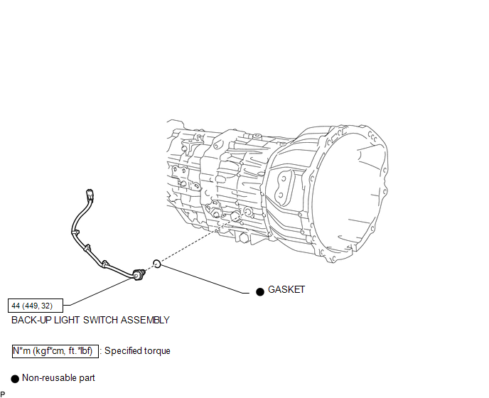
COMPONENTS
ILLUSTRATION
Inspection
INSPECTION
PROCEDURE
1. INSPECT BACK-UP LIGHT SWITCH ASSEMBLY
|
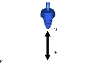
(a) Measure the resistance according to the value(s) in the table below. Text in Illustration
Standard Resistance:
If the result is not as specified, replace the back-up light switch assembly. |
|
Removal
REMOVAL
PROCEDURE
1. REMOVE SHIFT LEVER BOOT ASSEMBLY
.gif)
2. REMOVE BACK-UP LIGHT SWITCH ASSEMBLY
|
(a) Disconnect the connector. |
|
|
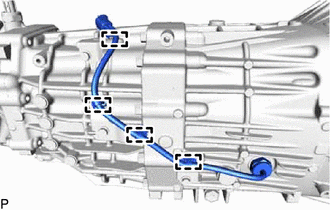
(b) Detach the 4 clamps. |
|
|
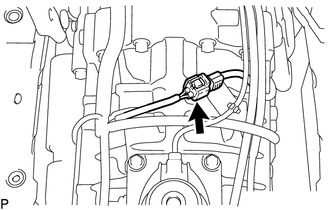
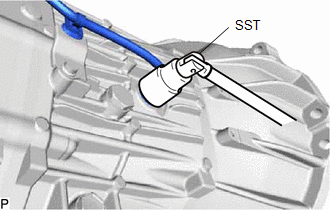
(c) Using SST, remove the back-up light switch assembly and gasket from the transmission case. SST: 09817-16011 |
|
Installation
INSTALLATION
PROCEDURE
1. INSTALL BACK-UP LIGHT SWITCH ASSEMBLY
|
(a) Using SST, install a new gasket and the back-up light switch assembly to the transmission case. SST: 09817-16011 Torque: 44 N·m {449 kgf·cm, 32 ft·lbf} |
|
.png)
(b) Attach the 4 clamps.
(c) Connect the connector.
2. INSTALL SHIFT LEVER BOOT ASSEMBLY
.gif)

 Counter Gear
...
Other materials:
Installation
INSTALLATION
PROCEDURE
1. INSTALL FRONT DISC
(a) Align the matchmarks of the front disc and the front axle hub and
install the front disc.
Text in Illustration
*a
Matchmark
HINT:
When replacing the disc with a new one, se ...
Removal
REMOVAL
PROCEDURE
1. REMOVE FRONT CONSOLE BOX
(See page )
2. DISCONNECT TRANSMISSION CONTROL CABLE ASSEMBLY
3. REMOVE TRANSMISSION CONTROL CABLE ASSEMBLY
(a) Remove the nut and clip and disconnect the transmission control cable
assembly from the automatic transmission assem ...
Parts Location
PARTS LOCATION
ILLUSTRATION
*A
for Automatic Transmission
*B
for Manual Transmission
*C
for 4WD
-
-
*1
FRONT SPEED SENSOR LH
*2
FRONT SPEED SENSOR RH
...
