Toyota Tacoma (2015-2018) Service Manual: Front Differential Oil Temperature Sensor Circuit High (P17C8)
DESCRIPTION
This DTC is output when a short to B+ or open circuit in the oil temperature sensor is detected.
|
DTC No. |
Detection Item |
DTC Detection Condition |
Trouble Area |
|---|---|---|---|
|
P17C8 |
Front Differential Oil Temperature Sensor Circuit High |
|
|
WIRING DIAGRAM
Refer to DTC P17C7 (See page .gif) ).
).
PROCEDURE
|
1. |
CHECK OIL TEMPERATURE SENSOR |
(a) Disconnect the 4 wheel drive control ECU connector.
|
(b) Measure the resistance according to the value(s) in the table below. Standard Resistance:
|
|
(c) Measure the voltage according to the value(s) in the table below.
Standard Voltage:
|
Tester Connection |
Switch Condition |
Specified Condition |
|---|---|---|
|
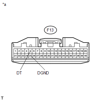
F13-5 (DT) or F13-25 (DGND) - Body ground |
Ignition switch ON |
Below 1 V |
|
*a |
Front view of wire harness connector (to 4 Wheel Drive Control ECU) |
| OK | .gif) |
REPLACE 4 WHEEL DRIVE CONTROL ECU |
|
.gif)
|
2. |
CHECK HARNESS AND CONNECTOR (4 WHEEL DRIVE CONTROL ECU - OIL TEMPERATURE SENSOR) |
(a) Disconnect the F13 4 wheel drive control ECU connector.
(b) Disconnect the F38 oil temperature sensor connector.
(c) Measure the resistance according to the value(s) in the table below.
Standard Resistance:
|
Tester Connection |
Condition |
Specified Condition |
|---|---|---|
|
F13-5 (DT) - F38-1 (DT) |
Always |
Below 1 Ω |
|
F13-25 (DGND) - F38-2 (DGND) |
Always |
Below 1 Ω |
(d) Measure the voltage according to the value(s) in the table below.
Standard Voltage:
|
Tester Connection |
Switch Condition |
Specified Condition |
|---|---|---|
|
F13-5 (DT) or F38-1 (DT) - Body ground |
Ignition switch ON |
Below 1 V |
|
F13-25 (DGND) or F38-2 (DGND) - Body ground |
Ignition switch ON |
Below 1 V |
| OK | |
REPLACE OIL TEMPERATURE SENSOR |
| NG | |
REPAIR OR REPLACE HARNESS OR CONNECTOR |
 Front Differential Oil Temperature Sensor Circuit Low (P17C7)
DESCRIPTION
This DTC is output when a short to ground in the oil temperature sensor is detected.
DTC No.
Detection Item
DTC Detection Condition
Trouble Ar ...
 Four Wheel Drive (4WD) Low Switch Circuit Range / Performance (P2772)
DESCRIPTION
This DTC is output when a malfunction in the L4 detection switch is detected.
DTC No.
Detection Item
DTC Detection Condition
Trouble Area
...
Other materials:
Front seats
Bench type seat
Seat position adjustment lever
Separated type seats
Seat position adjustment lever
Driver’s seat lumbar support adjustment
knob (if equipped)
Seatback angle adjustment lever ...
Portable Player cannot be Operated Using In-vehicle Device or Track Information
is not Displayed on In-vehicle Device
PROCEDURE
1.
CHECK USING ANOTHER "Bluetooth" AUDIO COMPATIBLE VEHICLE OF SAME MODEL
(a) Check if track information is displayed normally on another "Bluetooth" audio
compatible vehicle of the same model.
OK:
Track information is displayed no ...
Test Mode Procedure
TEST MODE PROCEDURE
1. TEST MODE PROCEDURE (for Using Techstream)
HINT:
If the ignition switch is turned from the ON to the ACC or LOCK position
during test mode, DTCs related to the signal check function will be cleared.
During test mode, the skid control ECU (master cylinder ...
