Toyota Tacoma (2015-2018) Service Manual: Four Wheel Drive (4WD) Low Switch Circuit Range / Performance (P2772)
DESCRIPTION
This DTC is output when a malfunction in the L4 detection switch is detected.
|
DTC No. |
Detection Item |
DTC Detection Condition |
Trouble Area |
|---|---|---|---|
|
P2772 |
Four Wheel Drive (4WD) Low Switch Circuit Range / Performance |
|
|
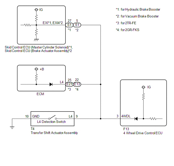
WIRING DIAGRAM
PROCEDURE
|
1. |
CHECK HARNESS AND CONNECTOR (4 WHEEL DRIVE CONTROL ECU - TRANSFER SHIFT ACTUATOR ASSEMBLY) |
(a) Disconnect the F13 4 wheel drive control ECU connector.
(b) Disconnect the T4 transfer shift actuator assembly connector.
(c) for Hydraulic Brake Booster:
Disconnect the S1 skid control ECU (Master Cylinder Solenoid) connector.
for Vacuum Brake Booster:
Disconnect the S1 skid control ECU (brake actuator assembly) connector.
(d) for 2TR-FE:
Disconnect the E21 ECM connector.
for 2GR-FKS:
Disconnect the E13 ECM connector.
(e) Measure the resistance according to the value(s) in the table below.
Standard Resistance:
|
Tester Connection |
Condition |
Specified Condition |
|---|---|---|
|
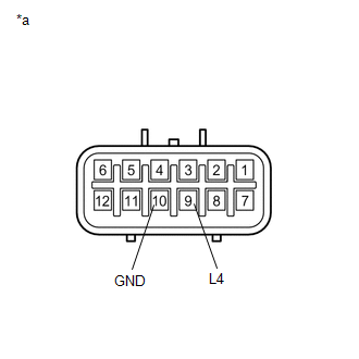
F13-3 (4WDL) - T4-9 (L4) |
Always |
Below 1 Ω |
|
T4-10 (GND) - Body ground |
Always |
Below 1 Ω |
|
F13-3 (4WDL) or T4-9 (L4) - Body ground |
Always |
10 kΩ or higher |
| NG | .gif) |
REPAIR OR REPLACE HARNESS OR CONNECTOR |
|
.gif)
|
2. |
CHECK TRANSFER SHIFT ACTUATOR ASSEMBLY |
(a) Turn the ignition switch to ON.
(b) Turn the transfer position switch to L4.
(c) Turn the ignition switch off.
(d) Disconnect the T4 transfer shift actuator assembly connector.
|
(e) Measure the resistance according to the value(s) in the table below. Standard Resistance:
|
|
| OK | |
REPLACE 4 WHEEL DRIVE CONTROL ECU |
| NG | |
REPLACE TRANSFER SHIFT ACTUATOR ASSEMBLY |
 Front Differential Oil Temperature Sensor Circuit High (P17C8)
DESCRIPTION
This DTC is output when a short to B+ or open circuit in the oil temperature
sensor is detected.
DTC No.
Detection Item
DTC Detection Condition
...
 Invalid Data Received From Vehicle Dynamics Control Module (U0416)
DESCRIPTION
This DTC is detected if a wheel speed malfunction signal is sent from the skid
control ECU (brake actuator assembly).
DTC No.
Detection Item
DTC Detect ...
Other materials:
Air conditioning filter
The air conditioning filter must be changed regularly to maintain air conditioning
efficiency.
■ Removal method
Turn the engine switch to the LOCK
position.
Open the glove box.
Slide off the damper.
Push in each side of the glove box to disconnect the claws.
Open the filter ...
Diagnostic Trouble Code Chart
DIAGNOSTIC TROUBLE CODE CHART
Air Conditioning System
DTC Code
Detection Item
Memory
See page
B1411/11
Room Temperature Sensor Circuit
Memorized
(4 seconds or more)
B1412/12
...
Disassembly
DISASSEMBLY
PROCEDURE
1. REMOVE OIL PUMP RELIEF VALVE
(a) Using a 27 mm socket wrench, remove the oil pump relief valve plug.
(b) Remove the oil pump relief valve spring and oil pump relief valve.
(c) Remove the spring and relief valve.
2. R ...
