Toyota Tacoma (2015-2018) Service Manual: Electrical Key Oscillator(for Rear Floor)
Components
COMPONENTS
ILLUSTRATION
Installation
INSTALLATION
PROCEDURE
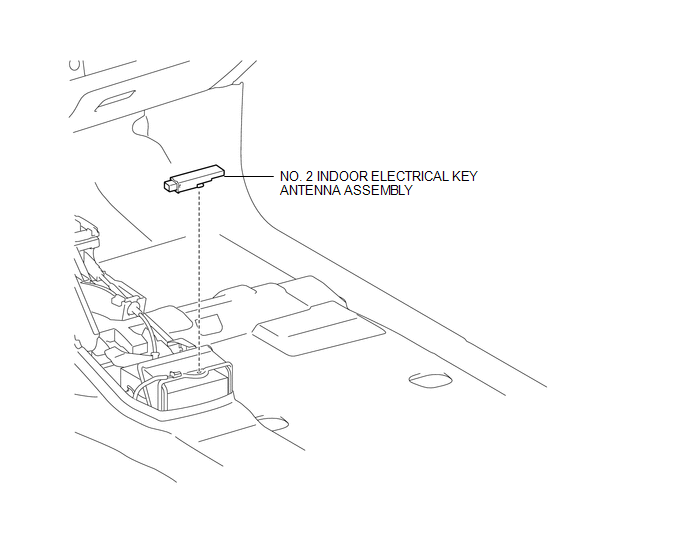
1. INSTALL NO. 2 INDOOR ELECTRICAL KEY ANTENNA ASSEMBLY
(a) Engage the clamp to install the No. 2 indoor electrical key antenna assembly.
(b) Connect the connector.
2. INSTALL REAR CONSOLE BOX ASSEMBLY
(See page .gif) )
)
Removal
REMOVAL
PROCEDURE
1. REMOVE REAR CONSOLE BOX ASSEMBLY
(See page .gif) )
)
2. REMOVE NO. 2 INDOOR ELECTRICAL KEY ANTENNA ASSEMBLY
|
(a) Disconnect the connector. |
|
(b) Using a clip remover, disengage the clamp to remove the No. 2 indoor electrical key antenna assembly.
 Electrical Key Oscillator(for Front Floor)
Components
COMPONENTS
ILLUSTRATION
Installation
INSTALLATION
PROCEDURE
1. INSTALL NO. 1 INDOOR ELECTRICAL KEY ANTENNA ASSEMBLY
(a) Engage the clamp to install the No. 1 indoor electrical ...

Other materials:
Terminals Of Ecu
TERMINALS OF ECU
1. CHECK ENGINE SWITCH
(a) Measure the resistance and voltage according to the value(s) in the table
below.
Terminal No. (Symbol)
Input/Output
Wiring Color
Terminal Description
Condition
Specified Condition
...
Illumination for Panel Switch does not Come on with Tail Switch ON
PROCEDURE
1.
CHECK VEHICLE SIGNAL (OPERATION CHECK)
(a) Enter the "Vehicle Signal Check Mode" screen. Refer to Check Vehicle Signal
in Operation Check (See page ).
(b) Check that the display changes between ON and OFF according to the light
control ...
Reassembly
REASSEMBLY
PROCEDURE
1. INSTALL FRONT AXLE HUB OIL SEAL
(a) Using a brass bar and a hammer, install a new front axle hub oil seal.
NOTICE:
Do not damage the oil seal.
2. INSTALL FRONT AXLE WITH ABS ROTOR BEARING ASSEMBLY
(a) Using SST and a press, install a new bearing onto the front axle ...
