Toyota Tacoma (2015-2018) Service Manual: Electrical Key Oscillator(for Front Floor)
Components
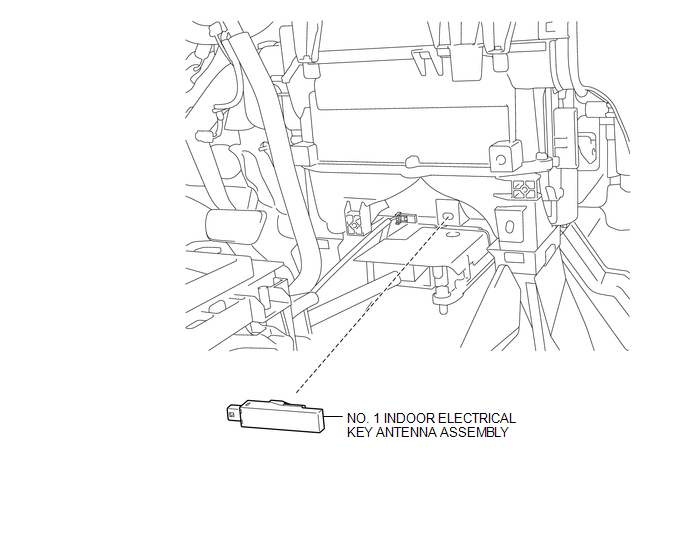
COMPONENTS
ILLUSTRATION
Installation
INSTALLATION
PROCEDURE
1. INSTALL NO. 1 INDOOR ELECTRICAL KEY ANTENNA ASSEMBLY
(a) Engage the clamp to install the No. 1 indoor electrical key antenna assembly.
(b) Connect the connector.
2. INSTALL FRONT CONSOLE BOX
(See page .gif) )
)
Removal
REMOVAL
PROCEDURE
1. REMOVE FRONT CONSOLE BOX
(See page .gif) )
)
2. REMOVE NO. 1 INDOOR ELECTRICAL KEY ANTENNA ASSEMBLY
|
(a) Disconnect the connector. |
|
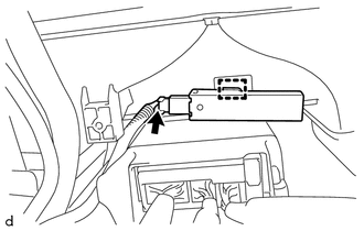
(b) Using a clip remover, disengage the clamp to remove the No. 1 indoor electrical key antenna assembly.
 Door Control Transmitter(w/ Smart Key System)
Components
COMPONENTS
ILLUSTRATION
Removal
REMOVAL
PROCEDURE
1. REMOVE TRANSMITTER BATTERY
Inspection
INSPECTION
PROCEDURE
1. INSPECT ELECTRICAL KEY TRANSMITTER SUB-ASSEMBLY
(a) ...
 Electrical Key Oscillator(for Rear Floor)
Components
COMPONENTS
ILLUSTRATION
Installation
INSTALLATION
PROCEDURE
1. INSTALL NO. 2 INDOOR ELECTRICAL KEY ANTENNA ASSEMBLY
(a) Engage the clamp to install the No. 2 indoor electrical ...
Other materials:
Terminals Of Ecu
TERMINALS OF ECU
1. CHECK 4 WHEEL DRIVE CONTROL ECU
Text in Illustration
*a
Component with harness connected
(4 Wheel Drive Control ECU)
-
-
(a) Measure the resistance and voltage according to the value(s) in the table
below.
...
Pressure Control Solenoid "D" Electrical (Shift Solenoid Valve SLT) (P2716)
DESCRIPTION
Refer to the system description for DTC P2714 (See page
).
DTC No.
DTC Detection Condition
Trouble Area
P2716
Open or short is detected in shift solenoid valve SLT circuit for 1 second
or more while driving (1 trip dete ...
Cruise Control Switch Circuit
DESCRIPTION
The cruise control main switch is used to turn the dynamic radar cruise control
system on and off, as well as operate 7 functions: SET, - (COAST), TAP-DOWN, RES
(RESUME), + (ACCEL), TAP-UP and CANCEL.
The SET, TAP-DOWN and - (COAST) functions, and the RES (RESUME), TAP-UP and +
( ...
