Toyota Tacoma (2015-2018) Service Manual: ECU Power Source Circuit
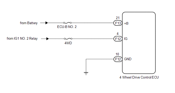
WIRING DIAGRAM
CAUTION / NOTICE / HINT
NOTICE:
Inspect the fuses for circuits related to this system before performing the following inspection procedure.
PROCEDURE
|
1. |
INSPECT BATTERY |
(a) Check the battery voltage.
Standard voltage:
11 to 14 V
| NG | .gif) |
CHECK OR REPLACE CHARGING SYSTEM OR BATTERY |
|
.gif)
|
2. |
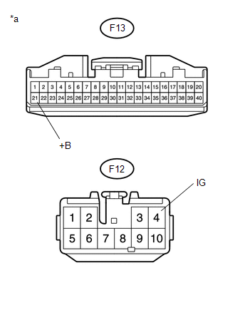
CHECK HARNESS AND CONNECTOR (+B AND IG TERMINAL) |
(a) Turn the ignition switch off.
|
(b) Disconnect the 4 wheel drive control ECU connector. |
|
(c) Measure the voltage according to the value(s) in the table below.
Standard Voltage:
|
Tester Connection |
Switch Condition |
Specified Condition |
|---|---|---|
|
F13-21 (+B) - Body ground |
Always |
11 to 14 V |
|
F12-4 (IG) - Body ground |
Ignition switch ON |
11 to 14 V |
|
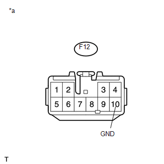
*a |
Front view of wire harness connector (to 4 Wheel Drive Control ECU) |
| NG | |
REPAIR OR REPLACE HARNESS OR CONNECTOR (+B OR IG CIRCUIT) |
|
|
3. |
CHECK HARNESS AND CONNECTOR (GND TERMINAL) |
(a) Turn the ignition switch off.
(b) Disconnect the 4 wheel drive control ECU connector.
|
(c) Measure the resistance according to the value(s) in the table below. Standard Resistance:
|
|
| OK | |
PROCEED TO NEXT SUSPECTED AREA SHOWN IN PROBLEM SYMPTOMS TABLE |
| NG | |
REPAIR OR REPLACE HARNESS OR CONNECTOR (GND CIRCUIT) |
 4WD ECU Malfunction (P163B)
DESCRIPTION
This DTC is output when a malfunction is detected in the 4 wheel drive control
ECU internal circuit.
DTC No.
Detection Item
DTC Detection Condition
...
 Lock Switch Circuit
WIRING DIAGRAM
PROCEDURE
1.
CHECK REAR DIFFERENTIAL LOCK INDICATOR LIGHT
(a) Turn the ignition switch to ON.
(b) for 4WD:
Finish switching to L4.
(c) Check the ...
Other materials:
System Diagram
SYSTEM DIAGRAM
Transmitting ECU (Transmitter)
Receiving ECU
Signal
Communication Method
Skid control ECU (Brake actuator assembly)
Steering angle sensor (Spiral cable with sensor sub-assembly)
Steering angl ...
Calibration
CALIBRATION
1. DESCRIPTION
(a) After replacing the VSC relevant components or performing "Front wheel alignment
adjustment", clearing and reading the sensor calibration data are necessary.
(b) Follow the chart to perform calibration.
Replacing Parts
Necessary Op ...
On-vehicle Inspection
ON-VEHICLE INSPECTION
PROCEDURE
1. INSPECT REFRIGERANT PRESSURE WITH MANIFOLD GAUGE SET
(a) This is a method to specify trouble areas by using a manifold gauge set.
Read the manifold gauge pressure when the following conditions are established.
Test conditions:
Engine has been warmed u ...
